Part Number: RM48L952
Other Parts Discussed in Thread: HALCOGEN,
I am attempting to follow TI data sheet (spna227.pdf) to trigger ADC1 with N2HET timer.
I need NHET to generate 48 kHz trigger signal.
Triggering ADC Using Internal Timer Events on Hercules MCUs
I understand this data sheet. I followed the example and created N2HET micromachine program using the HET Assembler.
The problem is, I don't know how to setup the following parameters to make the loop count correctly so the N2HET makes a periodic 48 kHz trigger signal.
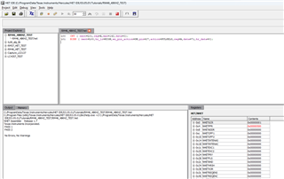
Here's my program, taken from TI Document (spna227.pdf)
L00 CNT {REG=A, max=8, data=0}
L01 ECMP {next=L00, hr_lr=HIGH, en_pin_action=ON, pin=8, action=PULSELO, reg=A, data=4, hr_data=0}
It looks like I might need to adjust some or all of the following parameters in one (or both) the HALCoGen and N2HET IDE, but I'm not sure how all the math works:
- In the HALCoGen
- in tab RM48L952 --> GCM
- VCLK2 Divider (to make VCLK2)
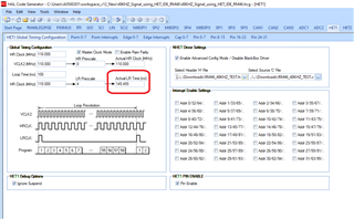
- in HET1 --> HET1 Global Timing Configuration
- HR Prescale
- LR Prescale
- (I tried to set these, but it looks like I need to set these in the HET IDE Assembler tool)
- in tab RM48L952 --> GCM
- In the HET IDE Assembler tool
- "max=8" (from program, L00, above)
- "data=4" (from program, L01, above)
Also, another big problem is when I change VCLK2 in the HALCoGen from the 100 MHZ default rate, the Hercules Development Kit we are using default 'C' code doesn't boot and hangs at the RAM initialization for the PCB. This seems strange to me but maybe changing the clock rate causes a timing problem with the default self test for HET peripheral? I'm not sure about this.
So far I spent about 3 days trying to figure this out, but I don't seem to understand the maths involved in the HET program and the HET clock divider circuits.
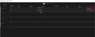
The good news is my test setup is working and I do see an 86.xxx kHZ periodic square wave on the output of N2HET1[8], so I know the loop is running, I just have wrong frequency.