Part Number: MSP432E411Y
Other Parts Discussed in Thread: UNIFLASH
Hi TI Experts,
I am using the MSP432E411Y MCU for an Ethernet-based application running on TI-RTOS. There is no physical access to the board except the power and ethernet connection, so the flash ethernet bootloader provided by TI will be used to update the software on the MSP432E411Y.
From the example provided for the MSP432E401Y Launchpad, my understanding is that the Ethernet bootloader in ROM is active when the main flash of the MSP432 is erased. We can use this to load the flash bootloader onto the MSP432 using BOOTP requests. When the device is reset, the flash bootloader sends BOOTP requests, which we can use to load the example application code.
The only difference between the example above and my project, is that my application is a ti-rtos project. It has the same magic packet listener routine and SoftwareUpdateBegin() function that the example uses, and it works to update the Application code over ethernet.
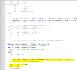
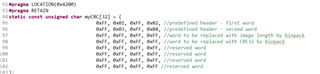
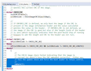
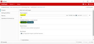
My understanding is that the application code, coupled with the ti-rtos build project it uses, changes the reset vectors of the device to make it start at the application code (0x4000?) after a reset. This application code is able to detect a "magic packet" sent by the TI BSL_Scripter application over ethernet and jump to executing the function stored in the SVCall register of the MSP432 (the bootloader has an assembly file in its project that sets a function called UpdateHandler to the SVCall register, if I am not mistaken). The function in the SVCall register sits in the bootloader and starts sending BOOTP requests for a software update. Once the software is received, it triggers a device resets which causes the MSP432 to start back at the new application code.
Please correct me if I am wrong about any of the steps in this process ^, I am trying to have a better understanding of what system registers change and how the 3 projects (bootloader, application, and ti-rtos build) link to each other.
The main issue I am having is that BSL_Scripter sometimes (about 10% of the time) fails with "[ACK_ERROR_MESSAGE] Unknown Error!", which corrupts my application software. If the board is reset, it tries to run the corrupt application again, which essentially results in a bricked MSP432, which can only be recovered with JTAG (not possible when you only have ethernet access to it).
Can you please help me figure out the following:
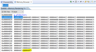
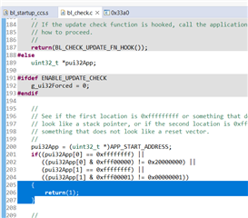
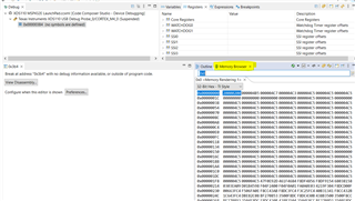
- Where does the reset vector sit in memory and how is it changed when we upload the application code?
- Is there a way to configure the reset vector in software, so we can modify it start running the application/bootloader as necessary?
- Do you have a solution for the MSP432 device being bricked when a BSL_Scripter ethernet software update fails?
Thanks.