Part Number: SW-EK-TM4C129EXL
Dear Sir,
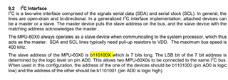
I want to receive accelerometer data from sensor MPU6050 using I2C. I can't get any data. What's my problem I don't understand? Is it initialization problem. Code is given below.
#include <stdint.h>
#include <stdbool.h>
#include <stdarg.h>
#include "inc/hw_ints.h"
#include "inc/hw_types.h"
#include "inc/hw_memmap.h"
#include "inc/hw_gpio.h"
#include "inc/hw_i2c.h"
#include "driverlib/sysctl.h"
#include "driverlib/gpio.h"
#include "driverlib/i2c.h"
#include "driverlib/pin_map.h"
//*****************************************************************************
//
//! \addtogroup example_list
//! <h1>Simple Project (project)</h1>
//!
//! A very simple example that can be used as a starting point for more complex
//! projects. Most notably, this project is fully TI BSD licensed, so any and
//! all of the code (including the startup code) can be used as allowed by that
//! license.
//!
//! The provided code simply toggles a GPIO using the Tiva Peripheral Driver
//! Library.
//
//*****************************************************************************
//*****************************************************************************
//
// The error routine that is called if the driver library encounters an error.
//
//*****************************************************************************
#ifdef DEBUG
void
__error__(char *pcFilename, uint32_t ui32Line)
{
}
#endif
/******************************
*
*/
uint32_t ui32SysClock;
//#define SlaveAddr 30
#define ACCEL_SLAVE_ADDR 0x1D
#define XOUT8 0x06
#define YOUT8 0x07
#define ZOUT8 0x08
//initialize I2C module 0
//Slightly modified version of TI's example code
void InitI2C0(void)
{
//enable I2C module 0
SysCtlPeripheralEnable(SYSCTL_PERIPH_I2C0);
//reset module
SysCtlPeripheralReset(SYSCTL_PERIPH_I2C0);
//enable GPIO peripheral that contains I2C 0
SysCtlPeripheralEnable(SYSCTL_PERIPH_GPIOB);
// Configure the pin muxing for I2C0 functions on port B2 and B3.
GPIOPinConfigure(GPIO_PB2_I2C0SCL);
GPIOPinConfigure(GPIO_PB3_I2C0SDA);
// Select the I2C function for these pins.
GPIOPinTypeI2CSCL(GPIO_PORTB_BASE, GPIO_PIN_2);
GPIOPinTypeI2C(GPIO_PORTB_BASE, GPIO_PIN_3);
// Enable and initialize the I2C0 master module. Use the system clock for
// the I2C0 module. The last parameter sets the I2C data transfer rate.
// If false the data rate is set to 100kbps and if true the data rate will
// be set to 400kbps.
I2CMasterInitExpClk(I2C0_BASE, ui32SysClock, false);
/*I2CMasterIntEnableEx(I2C0_BASE, (I2C_MASTER_INT_ARB_LOST |
I2C_MASTER_INT_STOP | I2C_MASTER_INT_NACK |
I2C_MASTER_INT_TIMEOUT | I2C_MASTER_INT_DATA));*/
//IntEnable(INT_I2C0);
//clear I2C FIFOs
HWREG(I2C0_BASE + I2C_O_FIFOCTL) = 80008000;
}
/*
* I2C receive function-------
*/
//read specified register on slave device
uint32_t I2CReceive(uint32_t slave_addr, uint8_t reg)
{
//specify that we are writing (a register address) to the
//slave device
I2CMasterSlaveAddrSet(I2C0_BASE, slave_addr, false);
//specify register to be read
I2CMasterDataPut(I2C0_BASE, reg);
//send control byte and register address byte to slave device
I2CMasterControl(I2C0_BASE, I2C_MASTER_CMD_BURST_SEND_START);
//wait for MCU to finish transaction
while(I2CMasterBusy(I2C0_BASE));
//specify that we are going to read from slave device
I2CMasterSlaveAddrSet(I2C0_BASE, slave_addr, true);
//send control byte and read from the register we
//specified
I2CMasterControl(I2C0_BASE, I2C_MASTER_CMD_SINGLE_RECEIVE);
//wait for MCU to finish transaction
while(I2CMasterBusy(I2C0_BASE));
//return data pulled from the specified register
return I2CMasterDataGet(I2C0_BASE);
}
uint8_t ReadAccel(uint8_t reg)
{
uint8_t accelData = I2CReceive(ACCEL_SLAVE_ADDR, reg);
return accelData;
}
//-------------------Main-----------------------------
int
main(void)
{
ui32SysClock = SysCtlClockFreqSet((SYSCTL_OSC_MAIN | SYSCTL_USE_PLL | SYSCTL_XTAL_25MHZ |
SYSCTL_CFG_VCO_480), 120000000);
InitI2C0();
uint8_t Ax, Ay, Az;
Ax = ReadAccel(XOUT8);
Ay = ReadAccel(YOUT8);
Az = ReadAccel(ZOUT8);
while(1){};
}