This thread has been locked.

If you have a related question, please click the "Ask a related question" button in the top right corner. The newly created question will be automatically linked to this question.

MSPM0G3507: Comparator high speed mode issue

Part Number: MSPM0G3507
Other Parts Discussed in Thread: SYSCONFIG

Hi,

I'm working on a project that applies a comparator to trigger the ADC routine using MSPM0G3507 Launchpad.
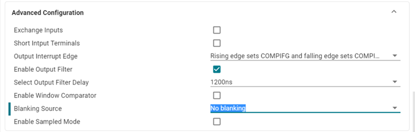
I used the example "comp_hs_dac_vref_external" to start my implementation. This example configures the comparator in high-speed mode using the 8-bit DAC with external reference as the positive input, and the external pin as the negative input.

I notice that the comparator triggers at the threshold set by the 8-bit DAC only for input signals with frequencies below 100 kHz. When I increased the frequency, the threshold didn't work properly, the transition of the comparator output started to occur for voltages different from the previous threshold value, eventually missing events for higher frequencies.


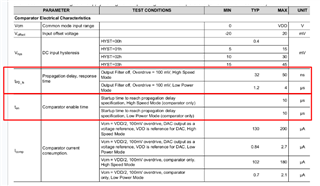
Looking at the figure attached on page 40 of the MSPM0G350x Mixed-Signal Microcontrollers, the comparator activation time parameter for high-speed mode is 10 us, and the propagation delay response time parameter for high-speed mode is 50 ns(max). My issues are the following:

1) Does the activation time occur only once and after the function "DL_COMP_enable(COMP_INST)"?

2) Is the propagation delay, response time parameter, the maximum time in which the comparator is able to "sense the inputs signals" and change the output accordingly?

3) Which parameters are needed to estimate the total comparison time?

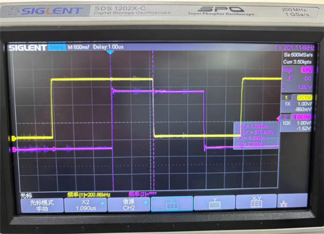
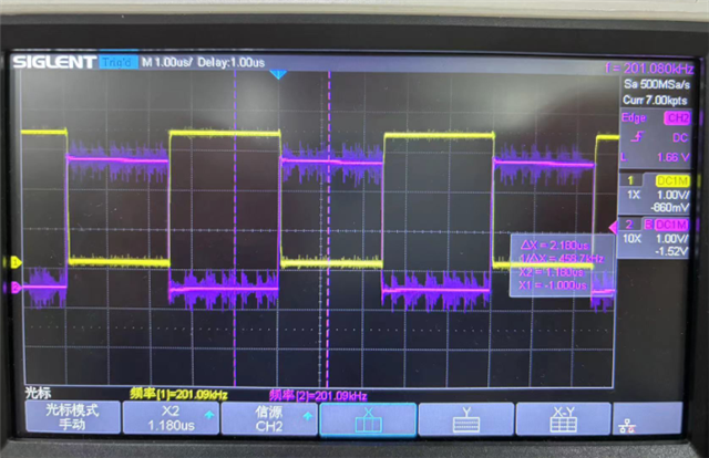
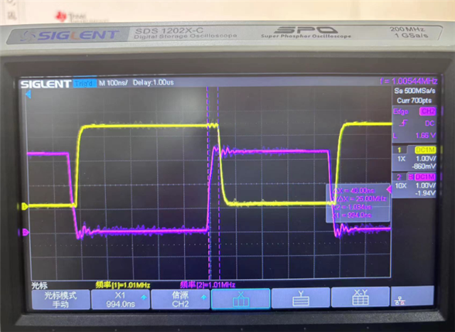
I have also attached an oscilloscope image for an external triangular wave (1 MHz) as a negative input (yellow) and an external pin indicator of the comparator result (blue).

thank you for the support.

  • Hi,

    Comparator enable time is the start-up time, and occur only once. And propagation delay, response time is the time between "sense the inputs signals" and change the output accordingly.

  • So why is the threshold value varying as a function of the aforementioned frequency and also why am I missing events at a frequency of 1 MHz?

  • Could you check that if you enable the filter. 

    We have tested the comp and it works well with high frequency signal. 

    My colleague will share it later in the thread.

  • Hi Yuhao,

    Can you share the explanation, please? We need to know what's going on in our implementation,

  • Hi,

    We have test the example "comp_hs_dac_vref_external" with a high frequency PWM input. And we think the phenomenon you said above is cause by the “Output Filter Delay”(refers to 11.2.4 section of MSPM0 G-Series Technical Reference Manual)  enablement, which is a default setting in this example, and it will bring 1200ns delay. 

    As a result, the 1200ns delay will be apparent when the input frequency up to 100kHz (T=10us), and below is the test result with input signal frequency = 200kHz (purple wave) and “Output Filter Delay” set as 1200ns, and there is an apparent delay in output wave(yellow wave).


    After disable “Output Filter Delay”, when the input frequency is 200kHz, the test result is show as the followed picture. There is nearly no delay in this frequency. 

    And we also measured the delay from input wave to output wave when disable output filter. And followed is the result when input PWM frequency is 1MHz. And the  propagation delay is about 40ns, which is consistent with the description in our datasheet.

    By the way, if you what to use our Comparator in a high frequency and care about the propagation delay a lot, there are another two setting you need to notice. One is the "Blanking Mode"(refers to 11.2.6 section), the other is "Comparator Hysteresis“(refers to 11.2.9 section). Both of them could be configured in sysconfig.