This thread has been locked.

If you have a related question, please click the "Ask a related question" button in the top right corner. The newly created question will be automatically linked to this question.

MCU-PLUS-SDK-AM263X: AM263x

Part Number: MCU-PLUS-SDK-AM263X
Other Parts Discussed in Thread: SYSCONFIG

when integrated WDT in open window, code works fine. When 50% is used as window size, the code gets reset within just 2 lines of printing. It does not work as needed. How to properly configure window watchdog.

uint8_t adc_soc_continuous_main(void *args)
{

/* Open drivers to open the UART driver for console */
Drivers_open();
Board_driversOpen();


DebugP_log("ADC Soc Continuous Test Started\r\n");

ADC_forceMultipleSOC(gAdc1baseAddr, 0xFFFF);
gpio_init();

DebugP_log("ADC 1 channel 0 output:\r\n");
DebugP_log("outside ADC 1 channel 0 output:\r\n");
while(1)
{
Watchdog_clear(gWatchdogHandle[CONFIG_WDT0]);
while(false == ADC_getInterruptStatus(gAdc1baseAddr, ADC_INT_NUMBER2));
ADC_clearInterruptStatus(gAdc1baseAddr, ADC_INT_NUMBER2);
gAdc1Result0[0] = ADC_readResult(gAdc1resultBaseAddr,ADC_SOC_NUMBER0);

DebugP_log("register value = \t%d ",gAdc1Result0[0]);
result=gAdc1Result0[0];
voltage=(result/4096)*3.2;
DebugP_log("voltage =%f\r\n",voltage);


if(voltage>2.9 && voltage<3.2)
{

DebugP_log("voltage high =%f\r\n",voltage);
GPIO_pinWriteHigh(gpioBaseAddr, pinNum1);
Watchdog_clear(gWatchdogHandle[CONFIG_WDT0]);
}
else if(voltage>0 && voltage<0.9)
{
DebugP_log("voltage low =%f \r \n",voltage);
return power_err;
}
else
{
DebugP_log("Transition Happened - function calling");
}

}

This is a power monitoring code. I have integrated watchdog timer in it. On 100% window( open window) it works as I intended. On using other window size, the code gets reset fastly. 

  • Hello Anandakrishnan,

    How are you changing from the 100% to 50% open Window?

    Are you doing so through SysConfig?

    If so can you post your SysConfig file before and after the change so we can review how the change was done?

    Best Regards,

    Ralph Jacobi

  • Yes, changing it by sysconfig. 

    /**
    * These arguments were used when this file was generated. They will be automatically applied on subsequent loads
    * via the GUI or CLI. Run CLI with '--help' for additional information on how to override these arguments.
    * @cliArgs --device "AM263x_beta" --package "ZCZ" --part "AM263x" --context "r5fss0-0" --product "MCU_PLUS_SDK_AM263x@09.00.00"
    * @versions {"tool":"1.18.0+3266"}
    */

    /**
    * Import the modules used in this configuration.
    */
    const adc = scripting.addModule("/drivers/adc/adc", {}, false);
    const adc1 = adc.addInstance();
    const gpio = scripting.addModule("/drivers/gpio/gpio", {}, false);
    const gpio1 = gpio.addInstance();
    const gpio2 = gpio.addInstance();
    const gpio3 = gpio.addInstance();
    const watchdog = scripting.addModule("/drivers/watchdog/watchdog", {}, false);
    const watchdog1 = watchdog.addInstance();
    const debug_log = scripting.addModule("/kernel/dpl/debug_log");
    const mpu_armv7 = scripting.addModule("/kernel/dpl/mpu_armv7", {}, false);
    const mpu_armv71 = mpu_armv7.addInstance();
    const mpu_armv72 = mpu_armv7.addInstance();
    const mpu_armv73 = mpu_armv7.addInstance();
    const mpu_armv74 = mpu_armv7.addInstance();

    /**
    * Write custom configuration values to the imported modules.
    */
    adc1.$name = "CONFIG_ADC1";
    adc1.soc0InterruptTrigger = "ADC_INT_SOC_TRIGGER_ADCINT2";
    adc1.soc1InterruptTrigger = "ADC_INT_SOC_TRIGGER_ADCINT2";
    adc1.soc2InterruptTrigger = "ADC_INT_SOC_TRIGGER_ADCINT2";
    adc1.soc3InterruptTrigger = "ADC_INT_SOC_TRIGGER_ADCINT2";
    adc1.soc4InterruptTrigger = "ADC_INT_SOC_TRIGGER_ADCINT2";
    adc1.soc5InterruptTrigger = "ADC_INT_SOC_TRIGGER_ADCINT2";
    adc1.soc6InterruptTrigger = "ADC_INT_SOC_TRIGGER_ADCINT2";
    adc1.soc7InterruptTrigger = "ADC_INT_SOC_TRIGGER_ADCINT2";
    adc1.soc8InterruptTrigger = "ADC_INT_SOC_TRIGGER_ADCINT1";
    adc1.soc9InterruptTrigger = "ADC_INT_SOC_TRIGGER_ADCINT1";
    adc1.soc10InterruptTrigger = "ADC_INT_SOC_TRIGGER_ADCINT1";
    adc1.soc11InterruptTrigger = "ADC_INT_SOC_TRIGGER_ADCINT1";
    adc1.soc12InterruptTrigger = "ADC_INT_SOC_TRIGGER_ADCINT1";
    adc1.soc13InterruptTrigger = "ADC_INT_SOC_TRIGGER_ADCINT1";
    adc1.soc14InterruptTrigger = "ADC_INT_SOC_TRIGGER_ADCINT1";
    adc1.soc15InterruptTrigger = "ADC_INT_SOC_TRIGGER_ADCINT1";
    adc1.soc0SampleWindow = 19;
    adc1.soc1SampleWindow = 19;
    adc1.soc2SampleWindow = 19;
    adc1.soc3SampleWindow = 19;
    adc1.soc4SampleWindow = 19;
    adc1.soc5SampleWindow = 19;
    adc1.soc6SampleWindow = 19;
    adc1.soc7SampleWindow = 19;
    adc1.soc8SampleWindow = 19;
    adc1.soc9SampleWindow = 19;
    adc1.soc10SampleWindow = 19;
    adc1.soc11SampleWindow = 19;
    adc1.soc12SampleWindow = 19;
    adc1.soc13SampleWindow = 19;
    adc1.soc14SampleWindow = 19;
    adc1.soc15SampleWindow = 19;
    adc1.enableInterrupt1 = true;
    adc1.enableInterrupt2 = true;
    adc1.enableConverter = true;
    adc1.adcClockPrescaler = "ADC_CLK_DIV_3_0";
    adc1.interrupt2SOCSource = "ADC_SOC_NUMBER15";
    adc1.interrupt1SOCSource = "ADC_SOC_NUMBER7";
    adc1.enableInterrupt2ContinuousMode = true;
    adc1.enableInterrupt1ContinuousMode = true;
    adc1.ADC.$assign = "ADC1";

    gpio1.$name = "CONFIG_GPIO0";
    gpio1.pinDir = "OUTPUT";
    gpio1.GPIO.gpioPin.$assign = "EPWM0_A";

    gpio2.pinDir = "OUTPUT";
    gpio2.$name = "CONFIG_GPIO58";
    gpio2.GPIO.gpioPin.$assign = "EPWM7_B";

    gpio3.$name = "AM263_U23_MUX_SEL_GPIO63";
    gpio3.GPIO.gpioPin.$assign = "EPWM10_B";

    watchdog1.$name = "CONFIG_WDT0";
    watchdog1.wdt_clk_src = "SOC_RcmPeripheralClockSource_XTALCLK";
    watchdog1.wdt_func_clk = 6250000;
    watchdog1.expirationTime = 5300;

    debug_log.enableUartLog = true;
    debug_log.uartLog.$name = "CONFIG_UART0";
    debug_log.uartLog.UART.RXD.$assign = "UART0_RXD";
    debug_log.uartLog.UART.TXD.$assign = "UART0_TXD";

    mpu_armv71.$name = "CONFIG_MPU_REGION0";
    mpu_armv71.size = 31;
    mpu_armv71.attributes = "Device";
    mpu_armv71.accessPermissions = "Supervisor RD+WR, User RD";
    mpu_armv71.allowExecute = false;

    mpu_armv72.$name = "CONFIG_MPU_REGION1";
    mpu_armv72.size = 15;
    mpu_armv72.accessPermissions = "Supervisor RD+WR, User RD";

    mpu_armv73.$name = "CONFIG_MPU_REGION2";
    mpu_armv73.baseAddr = 0x80000;
    mpu_armv73.size = 15;
    mpu_armv73.accessPermissions = "Supervisor RD+WR, User RD";

    mpu_armv74.$name = "CONFIG_MPU_REGION3";
    mpu_armv74.accessPermissions = "Supervisor RD+WR, User RD";
    mpu_armv74.baseAddr = 0x70000000;
    mpu_armv74.size = 21;

    /**
    * Pinmux solution for unlocked pins/peripherals. This ensures that minor changes to the automatic solver in a future
    * version of the tool will not impact the pinmux you originally saw. These lines can be completely deleted in order to
    * re-solve from scratch.
    */
    adc1.ADC.AIN0.$suggestSolution = "ADC1_AIN0";
    adc1.ADC.AIN1.$suggestSolution = "ADC1_AIN1";
    adc1.ADC.AIN2.$suggestSolution = "ADC1_AIN2";
    adc1.ADC.AIN3.$suggestSolution = "ADC1_AIN3";
    adc1.ADC.AIN4.$suggestSolution = "ADC1_AIN4";
    adc1.ADC.AIN5.$suggestSolution = "ADC1_AIN5";
    gpio1.GPIO.$suggestSolution = "GPIO0";
    gpio2.GPIO.$suggestSolution = "GPIO0";
    gpio3.GPIO.$suggestSolution = "GPIO0";
    debug_log.uartLog.UART.$suggestSolution = "UART0";

  • Hello Anandakrishnan,

    Thanks for providing this, I will get back to you on Friday after doing some testing on my end to try and re-create this issue.

    Best Regards,

    Ralph Jacobi

  • Hello Anandakrishnan,

    Thanks, with the details you provided, I can see what is happening with your setup.

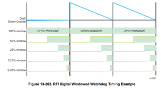
    The Windowed Watchdog operates by allowing only a certain window of time when the Watchdog timer can be reset. These windows are on the back half of the timer running:

    What you have set in SysConfig is a very long Watchdog, 5.3 seconds long, while your program code is going to execute significantly faster than this, and you are calling a Watchdog_clear each time the loop runs.

    The issue you have is due to this and how the Windowed Watchdog works. Specifically, "Any attempt to service the watchdog outside this time window, or a failure to service the watchdog in this time window, will cause the watchdog to generate either a reset or a non-maskable interrupt to the CPU." - Section 13.5.1.4.1 RTI Digital Windowed Watchdog of the TRM.

    So because your watchdog is in seconds but your code runs quickly, the you are triggering the reset by trying to service the watchdog outside the time window.

    To prove this, I added a ClockP_sleep(3); line above the Watchdog_clear in the while(1) loop to make the system wait 3 seconds before executing the clear each time the loop is entered. As the watchdog is 5.3 seconds long, this delay puts the device inside the 50% window, and at that point the code executes correctly once more.

    So if you want to use the Windowed Watchdog, you will have to fine tune your watchdog period to better reflect the time for your code to execute so that you are within the 50% window when the loop restart.

    Best Regards,

    Ralph Jacobi