Part Number: TMS570LC4357
Other Parts Discussed in Thread: TCA9535
goal is to read port 0 input pins of tca9535 .my doubt is to slave address api i should give 0x42 or 0x21.
second do i need to use 0x42 in senddata api for starting writing or just send command bytes for register.
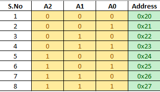
my slave address is 0x21 , command byte for configuration register is 0x06, command byte for input port register is 0x00.
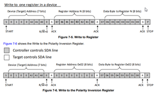
in the datasheet of tca9535 it says Reading from a target is very similar to writing, but requires some additional steps. In order to read from a target,the controller must first instruct the target which register it wishes to read from. This is done by the controller
starting off the transmission in a similar fashion as the write, by sending the address with the R/ W bit equal to
0 (signifying a write), followed by the register address it wishes to read from. When the target acknowledges this
register address, the controller sends a START condition again, followed by the target address with the R/ W
bit set to 1 (signifying a read). This time, the target acknowledges the read request, and the controller releases
the SDA bus but continues supplying the clock to the target. During this part of the transaction, the controller
becomes the controller-receiver, and the target becomes the target-transmitter.
The controller continues to send out the clock pulses, but releases the SDA line so that the target can transmit
data. At the end of every byte of data, the controller sends an ACK to the target, letting the target know that it
is ready for more data. When the controller has received the number of bytes it is expecting, it sends a NACK,
signaling to the target to halt communications and release the bus. The controller follows this up with a STOP
condition.
After a restart, the value of the register defined by the command byte matches the register being accessed when
the restart occurred. For example, if the command byte references Input Port 1 before the restart, and the restart
occurs when Input Port 0 is being read, the stored command byte changes to reference Input Port 0. The original
command byte is forgotten. If a subsequent restart occurs, Input Port 0 is read first. Data is clocked into the
register on the rising edge of the ACK clock pulse. After the first byte is read, additional bytes may be read, but
the data now reflect the information in the other register in the pair. For example, if Input Port 1 is read, the next
byte read is Input Port 0.
Data is clocked into the register on the rising edge of the ACK clock pulse. There is no limitation on the number
of data bytes received in one read transmission, but when the final byte is received, the bus controller must not
acknowledge the data.
uint8_t TX_Data_Master[3] = {0x42,0x00,0x43};
uint8_t configData[2]={/*0x42,*/0x06,0xFF}; // Array to hold configuration data
/
int main(void)
{
/* USER CODE BEGIN (3) */
int i;
int repeat = 0;
int delay =0;
i2cInit();
sciInit();
i2c_io_exp_init();
// Master Receive Functionality //
/* Configure address of Slave to talk to */
i2cSetSlaveAdd(i2cREG2, 0x42);
/* Set direction to receiver */
i2cSetDirection(i2cREG2, I2C_RECEIVER);
for(repeat = 0; repeat < 2; repeat++)
{
/* Configure Data count */
/* Note: Optional - It is done in Init, unless user want to change */
i2cSetCount(i2cREG2, 3);
/* Set mode as Master */
i2cSetMode(i2cREG2, I2C_MASTER);
/* Set Stop after programmed Count */
i2cSetStop(i2cREG2);
/* Transmit Start Condition */
i2cSetStart(i2cREG2);
/* Tranmit DATA_COUNT number of data in Polling mode */
i2cReceive(i2cREG2, 1, io_receive_data);
/* Wait until Bus Busy is cleared */
while(i2cIsBusBusy(i2cREG2) == true);
/* Wait until Stop is detected */
while(i2cIsStopDetected(i2cREG2) == 0);
/* Clear the Stop condition */
i2cClearSCD(i2cREG2);
for (i = 0; i < IO_DATA_SIZE; i++)
{
printBits(io_receive_data[i]);
}
/* Simple Dealya before starting Next Block */
/* Depends on how quick the Slave gets ready */
for(delay=0;delay<1000000;delay++);
}
/ Function to configure pins on Port 0 as inputs
void configurePort0AsInputs() {
i2cSetSlaveAdd(i2cREG2,0x21); /* Set the slave address */
i2cSetDirection(i2cREG2, I2C_TRANSMITTER); /* Set direction to Transmitter */
/* Configure Data count */
i2cSetCount(i2cREG2, 2);
i2cSetMode(i2cREG2, I2C_MASTER); /* Set mode as Master */
i2cSetStop(i2cREG2);
i2cSetStart(i2cREG2); /* Generate the start condition */
/* Tranmit DATA_COUNT number of data in Polling mode */
i2cSend(i2cREG2, 2, configData);
/* Wait until Bus Busy is cleared */
while(i2cIsBusBusy(i2cREG2) == true);
/* Wait until Stop is detected */
while(i2cIsStopDetected(i2cREG2) == 0);
/* Clear the Stop condition */
i2cClearSCD(i2cREG2);
}
void i2c_io_exp_init()
{
configurePort0AsInputs();
i2cSetCount(i2cREG2,3);
/* Set Stop after programmed Count */
i2cSetStop(i2cREG2);
i2cSetStart(i2cREG2); /* Generate the start condition */
/* Transfer the data bytes */
i2cSend(i2cREG2,3,TX_Data_Master);
/* Wait until Bus Busy is cleared */
while(i2cIsBusBusy(i2cREG2) == true);
/* Wait until Stop is detected */
while(i2cIsStopDetected(i2cREG2) == 0);
/* Clear the Stop condition */
i2cClearSCD(i2cREG2);
}