Part Number: TM4C1290NCPDT
I'm trying to read a byte of data as Master. So the I2C bus should send 1) the device I2C address, 2) send the register number being accessed, 3) read the value being returned. Code as follows:
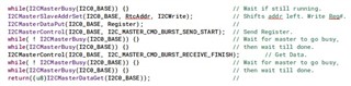
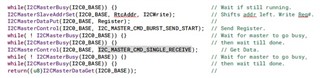
u8 RtcRead(u8 Register) { //
//
while(I2CMasterBusy(I2C0_BASE)) {} // Wait if still running.
I2CMasterSlaveAddrSet(I2C0_BASE, RtcAddr, I2CRead); // This shifts the addr left 1.
I2CMasterDataPut(I2C0_BASE, Register); //
I2CMasterControl(I2C0_BASE, I2C_MASTER_CMD_SINGLE_SEND); // Send Register.
while( ! I2CMasterBusy(I2C0_BASE)) {} // Wait for master to go busy,
while(I2CMasterBusy(I2C0_BASE)) {} // then wait till done.
I2CMasterControl(I2C0_BASE, I2C_MASTER_CMD_SINGLE_RECEIVE); // Get Data.
while( ! I2CMasterBusy(I2C0_BASE)) {} // Wait for master to go busy,
while(I2CMasterBusy(I2C0_BASE)) {} // then wait till done.
return(I2CMasterDataGet(I2C0_BASE)); //
} //
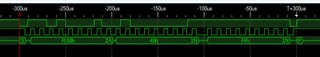
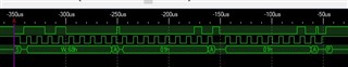
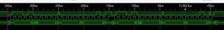
Here's what happens on the I2C bus, not the NAK on the second byte as 0x40 is an invalid register number:
Thanks, Doug
P.S. I wish there was a much better writeup on using the I2C than in the TivaWare manual - and the examples haven't been of that much help. Aren't there a lot of folks using the TM4C parts and I2C?