Other Parts Discussed in Thread: UNIFLASH, MSP-GANG, MSP-FET
Hello Team,
I was referring to the user guide SLAU748B for one of our designs with MSP432E401YTPDTR controller.
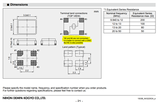
Ideally the shield of the crystal must me connected to the GND for better noise performance.
Please correct me if I am wrong.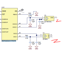
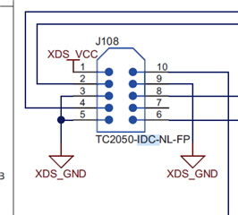
Why these pins are not connected to GND?
Also, is there any problems if we connect the shield pins of the RJ45 connector and USB connectors together and connecting them to chassis GND?.
Looking for your reply.