This thread has been locked.

If you have a related question, please click the "Ask a related question" button in the top right corner. The newly created question will be automatically linked to this question.

RM57L843: NHET Digital Loopback Configuration

Part Number: RM57L843
Other Parts Discussed in Thread: HALCOGEN

Hello,

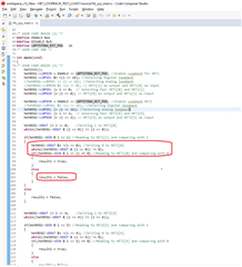
How do I create a NHET digital loopback? 

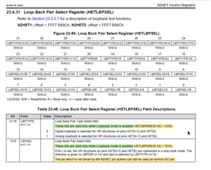
HalCoGen creates PWM functions with 1 pin each and Capture functions with 2 pins each. The Loop Back Pair Select Register (HETLBPSEL) and Loop Back Pair Direction Register (HETLBPDIR) configure pairs of consecutive pins (HET[n] and HET[n+1]). 

Regards,

Marcio.

  • Hi Marcio,

    Please refer below attached project:

    5736.HET_LOOPBACK_TEST_LC4357.zip

    Here i wrote code to test both either analog or digital loopback on the on (HET1[0] & HET1[1]) and (HET2[4] & HET2[5]).

    Here are the steps i followed:

    1. First i enabled the loopback:

    2. After enabling loopback, now i am selecting type of loopback either digital or analog:

    3. Once you select the required loopback, now select the loopback pairs and their directions.

    4. Now first write logic-1 to the output pin and verify you are reading the same on your input pin.

    If the reading value is not logic-1 then mark it as error.

    5. If we read logic-1 successfully then i am writing logic-0

    If logic-0 is also successful then i am making the status as true, if either of the logic failed then marking as false.

    --
    Thanks & regards,
    Jagadish.

  • Thanks Jagadish for the explanations.

    Maybe is not possible to do what I want to do. 

    I have configure the HET with a PWM and a Capture functions using HalCoGen. I would like to make the Capture function to read the PWM signal using the digital loopback. 

    Best regards

  • Hi Marcio,

    I have configure the HET with a PWM and a Capture functions using HalCoGen. I would like to make the Capture function to read the PWM signal using the digital loopback. 

    I never tested in this way, but you can give a try. I mean the loopback and PWM functions are different, not depend on each other as far as i understand.

    So, you can do the loopback process as i mentioned above and then you can generate the PWM and capture functions on required pins. 

    But the important thing is that, the PWM and capture function pins should be adjacent to each other, because the loopback pairs will only happen with adjacent pins.

    As you can see loopback pairs are HET[1] and HET[0], HET[3] and HET[2], HET[5] and HET[4]........etc

    So, if you are doing capture functionality on HET[0] then generate PWM signal on HET[1] and then loopback both using the procedure i mentioned.

    This is way you can do that, if this process doesn't work then we should use external loopback only.

    --

    Thanks & regards,
    Jagadish.