This thread has been locked.

If you have a related question, please click the "Ask a related question" button in the top right corner. The newly created question will be automatically linked to this question.

MSPM0L1305: How to inform an I2C target to release the I2C bus? (SDA stuck low)

Part Number: MSPM0L1305
Other Parts Discussed in Thread: BQ76952

Hi,

Background:

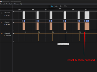
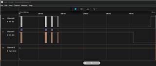
I am currently working with a custom board that features an MSPM0L1305 as the main MCU, communicating with two BQ76952 chips via I2C. Upon resetting the MCU, I sometimes observe the I2C bus getting stuck low, causing the program to hang indefinitely while waiting to exit the "bus busy" state. The I2C bus only recovers when I completely reset the BQ76952 chips by disconnecting and reconnecting the power.

Question:

Is there any way the host MCU can inform the targets (BQ76952) to release the bus in this situation?

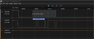
I was informed that the controller generating 9-10 scl cycles will do the trick. If this is a recommended solution, can you please provide the correct way to generate a certain number of clock cycles?

Thank you,

Kyungjae Lee

  • Hi Kyungjae,

    Typically it is the I2C target device that creates the clock stretch (holds SCL low), so in this case one, or both of the BQ76952 devices is not ready to respond and will hold the SCL line low.  There isn't much the MSMP0 can do to recover from this scenario.  As you mentioned, the only way to completely recover is to cycle power on the BQ devices.

    Can you isolate the BQ devices from the I2C bus - in other words can you run only one at a time to see if the problem is related to one specific BQ? Can you monitor the I2C bus and see what command or transaction is causing the BQ to enter the clock stretch mode?

  • Hi Dennis,

    To clarify, it is not the SCL line that is held low, but the SDA line. (I already have a workaround for the SCL being held low using the "Timeout A" feature of the MCU.)

    To answer your questions, this issue does not occur by itself while the program is running. It only happens occasionally when I reset the MCU by pressing the reset button on the board while the program is running. It seems to me that there is a specific timing that causes this behavior.

    The current program is written to communicate with only one of the two AFEs and here are some snapshots that shows the moment the behavior is caught.

    The very last part of the communication zoomed in:

    The very last part even further zoomed in:

    Hope this helps!

    Thank you,

    Kyungjae Lee

  • Hi Kyungjae,

    Based on the last two images, I suspect what may be happening is when you reset the MSMP0 in the middle of an I2C transaction, this leaves the BQ device in some incomplete read or write state. A valid transaction requires an I2C START condition as well as an I2C STOP condition for any I2C device on the bus.  After the MSMP0 reset, the MSPM0 starts sending a new transaction to the BQ but the BQ needs to see an I2C STOP bit from previous transaction before it can start processing this new transaction.  I was going to suggest trying to create an I2C STOP condition first with the MSPM0 I2C pins configured as GPIO, then re-configure them as I2C.  But that won't work if the state of the I2C bus is such that the BQ device was in the middle of clocking data out on the SDA line because the MSPM0 won't be able to control the SDA while the BQ device is in this state.

    I assume resetting the MSMP0 only happens as part of your development/debug and in real operation both MSPM0 and the BQ devices go through a reset, as when they are first powered on, correct?

    Can you post the Saleae .sal capture file of the waveforms you shared?

  • If the target is holding (only) SDA low, you can switch SCL to GPIO and send (8+1) clock pulses. At one of those pulses, the target will release SDA, and the following pulse will be seen as a NACK.

    This is described in the I2C spec (UM10204 rev 7) Sec 3.1.16 ("Bus Clear"). 

  • Hi Dennis,

    I think your explanation is spot on. It perfectly aligns with what I have been observing.

    To answer your question, yes resetting the MSPM0 only happens as part of our development/debug process. In real operation, the MCU-only reset is unlikely to happen once the program is up and running, but I still feel it necessary to implement the "bus clear" logic in the beginning of the program so when I need to reset the MCU in the field for some reason, I wouldn't have to worry about this.

    Also, please find the .sal capture file attached. (https://drive.google.com/file/d/1rK8iIzxLhdUiE9--ED9gjLBml__UpxOc/view?usp=drive_link)

    Thank you,

    Kyungjae Lee

  • Hi Bruce,

    Thank you for your insights and directing me to the documentation. It sounds like all I need to do to generate the clock pulses is to temporarily switch the SCL pin to GPIO output pin and toggle it multiple times to simulate (8+1) clock pulses. Am I correct?

    Thank you,

    Kyungjae Lee

  • Yes. Configuring SCL as an output (GPIO) is fine, since you're the master (and you know SCL is free). 

    I recommend sending all 9 pulses -- any extra pulses will be ignored (due to the NACK).

    I've used this to recover from exactly the kind of condition (master "vanishes" mid-transaction) that Dennis has described.

  • Thank you very much Bruce - I was not aware of this.

    Kyungjae - please try this and let us know if this works for you.

  • Hi Dennis,

    Since I was able to clear the bus by manually shorting the SCL line to GND a couple of times (to simulate 8+1 clock cycles), I am pretty sure what Bruce suggested will work as well.

    Also, for the benefit of other people facing similar situations, I'd like to share another solution  suggested in a different section of the forum. BQ76952: How to inform the target (bq76952) to release the I2C bus? (SDA stuck low)

    Appreciate you all!

    Best regards,

    Kyungjae Lee