Part Number: MSPM0G1505
Tool/software:
Using inbuilt DAC and have calibrated it. Now how can I use the DAC for mass manufacturing 1000 boards ? Each DAC will have different calibration values right?
This thread has been locked.
If you have a related question, please click the "Ask a related question" button in the top right corner. The newly created question will be automatically linked to this question.
Part Number: MSPM0G1505
Tool/software:
Using inbuilt DAC and have calibrated it. Now how can I use the DAC for mass manufacturing 1000 boards ? Each DAC will have different calibration values right?
Hello Sureshan,
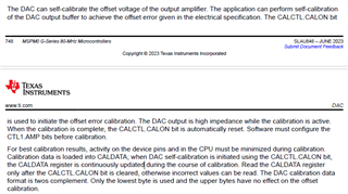
The calibration you mentioned is the output amplifier offset calibration, right? The DAC of M0 can self-calibrate the offset voltage of the output amplifier. You can try to write the DAC self-calibrate code and download it into M0. The final result of self-calibration will be saved in the CALDATA register, when you need it, you can read out it. The specific information of DAC self-calibration can be found in the chapter 14 of the M0 G series user guide which can be downloaded from ti.com.

Best Regards,
Janz Bai
Ok so does this mean I will get 0v when DAC value is zero .I am seeing a positive offset. When I give 0 as lsb I get 0.03v as dac output. And what about the gain error ? Is that too compensated with this method or I will have to do it in my code?
I want a signal of 0-2.4v with linearity mainted as dac_out. Right now because of offset I have planned to use a opamp that will convert the offset to zero and 2.43 to 2.4v
Hello Sureshan,
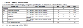
The method mentioned in the user guide just can achieve the offset error mentioned in the datasheet, not must get 0V when DAC value is zero. The gain error you can find in the datasheet too, please go to check the datasheet of G150x. It is not necessary for you to add this self-calibrated method in your code, our user guide just provide a method for self-calibration. If the results through your own calibration method can meet your requirement, it is OK enough. And in theory, you need to calibrate each chip if you want to get accurate value because each chip may have different calibration value.

Best Regards,
Janz Bai
Conclusion:
ok so if I want to make 1000 chips then the right way is to do a self calibration in the code itself right? It will take care of the offset and gain error . That means from 0.3v to 3v my signal will be linear and calibrated for any mcu that runs the code. And I wont get a 0-2.4v linear signal directly from dac ,right? I will get linearity from 0.3v to 2.7v from the dac_out , right ? Which means I will have to add a circuit to convert [0.3v-2.7v] to [0-2.4v] ,right?
Hello Sureshan,
1). if you want to calibrate 1000 chips, calibrating one by one is one method, using the self-calibration is another method. According to our datasheet, if you don't do any calibration for the DAC, the offset is just -20~20 mV, if you do self-calibration, you can get offset -2~2 mV, and the typical value is 0.5 mV.
2). we take VDD=3.3 V as a reference. Because of the offset, if the DAC value is 0x0, you may get 0+0.5mV value. Because of the offset, you may get the reference value when your DAC haven't rise to the full-scale code. So the datasheet says that the valid output range is 0.3~ VDD-0.3. But it doesn't mean you can get the 0V output and reference voltage output. I remember that it seems that you can get 0 V output. I recommend you to do some tests of the DAC output and you will get more intuitive understanding.
Best Regards,
Janz Bai