Part Number: EK-TM4C1294XL
Tool/software:
Hi,
I am new to TM4C1294xl board trying to enable ssi pheripheral to bmp sensor can anyone guide me
Also trying to examples codes C:\ti\TivaWare_C_Series-2.2.0.295\examples\boards\ek-tm4c1294xl\ssi_master_slave_xfer for SPI pheripheral but how to prove its working spi i dont know
So i decided to connect external sensor BMP280 sensor in this case I2C has wroking read temperature appear
I want SPI pheripheral to read temperature sensor data
This is my code
#include <stdint.h>
#include <stdbool.h>
#include <math.h>
#include "inc/hw_memmap.h"
#include "inc/hw_types.h"
#include "inc/hw_ints.h"
#include "driverlib/debug.h"
#include "driverlib/gpio.h"
#include "driverlib/interrupt.h"
#include "driverlib/pin_map.h"
#include "driverlib/sysctl.h"
#include "driverlib/systick.h"
#include "driverlib/uart.h"
#include "driverlib/ssi.h"
#include "driverlib/ssi.c"
#include "sensorlib/i2cm_drv.h"
#include "sensorlib/i2cm_drv.c"
#include "bmp280.h"
#include "driverlib/i2c.h"
#include "utils/uartstdio.h"
#include "utils/uartstdio.c"
#define BMP280_API
/*Enable the macro BMP280_API to use this support file */
/*----------------------------------------------------------------------------*
* The following functions are used for reading and writing of
* sensor data using I2C or SPI communication
*----------------------------------------------------------------------------*/
#ifdef BMP280_API
/* \Brief: The function is used as I2C bus read
* \Return : Status of the I2C read
* \param dev_addr : The device address of the sensor
* \param reg_addr : Address of the first register, where data is going to be read
* \param reg_data : This is the data read from the sensor, which is held in an array
* \param cnt : The no of bytes of data to be read
*/
s8 BMP280_I2C_bus_read(u8 dev_addr, u8 reg_addr, u8 *reg_data, u8 cnt);
/* \Brief: The function is used as I2C bus write
* \Return : Status of the I2C write
* \param dev_addr : The device address of the sensor
* \param reg_addr : Address of the first register, where data is to be written
* \param reg_data : It is a value held in the array,
* which is written in the register
* \param cnt : The no of bytes of data to be written
*/
s8 BMP280_I2C_bus_write(u8 dev_addr, u8 reg_addr, u8 *reg_data, u8 cnt);
/*
* \Brief: I2C init routine
*/
s8 I2C_routine(void);
#endif
/********************End of I2C/SPI function declarations***********************/
/* Brief : The delay routine
* \param : delay in ms
*/
void BMP280_delay_msek(u32 msek);
/* This function is an example for reading sensor data
* \param: None
* \return: communication result
*/
s32 bmp280_data_readout_template(void);
/*----------------------------------------------------------------------------*
* struct bmp280_t parameters can be accessed by using bmp280
* bmp280_t having the following parameters
* Bus write function pointer: BMP280_WR_FUNC_PTR
* Bus read function pointer: BMP280_RD_FUNC_PTR
* Delay function pointer: delay_msec
* I2C address: dev_addr
* Chip id of the sensor: chip_id
*---------------------------------------------------------------------------*/
struct bmp280_t bmp280;
//****************************************************************************
//
// System clock rate in Hz.
//
//****************************************************************************
uint32_t g_ui32SysClock;
//*****************************************************************************
//
// Global instance structure for the I2C master driver.
//
//*****************************************************************************
tI2CMInstance g_sI2CInst;
//*****************************************************************************
//
// Global new data flag to alert main that BMP180 data is ready.
//
//*****************************************************************************
volatile uint_fast8_t g_vui8DataFlag;
/* The variable used to assign the standby time*/
u8 v_standby_time_u8 = BMP280_INIT_VALUE;
/* The variables used in individual data read APIs*/
/* The variable used to read uncompensated temperature*/
s32 v_data_uncomp_tem_s32 = BMP280_INIT_VALUE;
/* The variable used to read uncompensated pressure*/
s32 v_data_uncomp_pres_s32 = BMP280_INIT_VALUE;
/* The variable used to read real temperature*/
s32 v_actual_temp_s32 = BMP280_INIT_VALUE;
/* The variable used to read real pressure*/
u32 v_actual_press_u32 = BMP280_INIT_VALUE;
/* The variables used in combined data read APIs*/
/* The variable used to read uncompensated temperature*/
s32 v_data_uncomp_tem_combined_s32 = BMP280_INIT_VALUE;
/* The variable used to read uncompensated pressure*/
s32 v_data_uncomp_pres_combined_s32 = BMP280_INIT_VALUE;
/* The variable used to read real temperature*/
s32 v_actual_temp_combined_s32 = BMP280_INIT_VALUE;
/* The variable used to read real pressure*/
u32 v_actual_press_combined_u32 = BMP280_INIT_VALUE;
float temp ;
int tempInt1;
float tempFrac;
int tempInt2;
float pres;
int presInt1;
float presFrac;
int presInt2;
/* result of communication results*/
s32 com_rslt = ERROR;
//*****************************************************************************
//
// The error routine that is called if the driver library encounters an error.
//
//*****************************************************************************
#ifdef DEBUG
void
__error__(char *pcFilename, uint32_t ui32Line)
{
}
#endif
//*****************************************************************************
//
// BMP180 Sensor callback function. Called at the end of BMP180 sensor driver
// transactions. This is called from I2C interrupt context. Therefore, we just
// set a flag and let main do the bulk of the computations and display.
//
//*****************************************************************************
void BMP280AppCallback(void* pvCallbackData, uint_fast8_t ui8Status)
{
//
// If the transaction was successful then set the data ready flag.
if(ui8Status == I2CM_STATUS_SUCCESS)
{
g_vui8DataFlag = 1;
}
//
// Turn off the LED to show read is complete.
//
}
//*****************************************************************************
//
// Called by the NVIC as a result of I2C7 Interrupt. I2C7 is the I2C connection
// to the BMP180.
//
// This handler is installed in the vector table for I2C7 by default. To use
// the SensHub on BoosterPack 2 interface change the startup file to place this
// interrupt in I2C8 vector location.
//
//*****************************************************************************
void
BMP280I2CIntHandler(void)
{
//
// Pass through to the I2CM interrupt handler provided by sensor library.
// This is required to be at application level so that I2CMIntHandler can
// receive the instance structure pointer as an argument.
//
I2CMIntHandler(&g_sI2CInst);
}
//*****************************************************************************
//
// Configure the UART and its pins. This must be called before UARTprintf().
//
//*****************************************************************************
void
ConfigureUART(void)
{
//
// Enable the GPIO Peripheral used by the UART.
//
SysCtlPeripheralEnable(SYSCTL_PERIPH_GPIOA);
//
// Enable UART0.
//
SysCtlPeripheralEnable(SYSCTL_PERIPH_UART2);
//
// Configure GPIO Pins for UART mode.
//
GPIOPinConfigure(GPIO_PA6_U2RX);
GPIOPinConfigure(GPIO_PA7_U2TX);
GPIOPinTypeUART(GPIO_PORTA_BASE, GPIO_PIN_6 | GPIO_PIN_7);
//
// Initialize the UART for console I/O.
//
UARTStdioConfig(2, 115200, g_ui32SysClock);
UARTprintf("<-----Configuring UART------>");
}
void
ConfigureI2CDriver(void){
//
// The I2C0 peripheral must be enabled before use.
//
//
SysCtlPeripheralEnable(SYSCTL_PERIPH_SSI1);
SysCtlPeripheralEnable(SYSCTL_PERIPH_GPIOB);
SysCtlPeripheralEnable(SYSCTL_PERIPH_GPIOE);
SysCtlDelay(2);
//
// Configure the pin muxing for I2C0 functions on port D0 and D1.
// This step is not necessary if your part does not support pin muxing.
//
//
GPIOPinConfigure(GPIO_PB4_SSI1FSS);
GPIOPinConfigure(GPIO_PB5_SSI1CLK);
GPIOPinConfigure(GPIO_PE4_SSI1XDAT0);
GPIOPinConfigure(GPIO_PE5_SSI1XDAT1);
SysCtlDelay(2);
//
// Select the I2C function for these pins. This function will also
// configure the GPIO pins for I2C operation, setting them to
// open-drain operation with weak pull-ups. Consult the data sheet
// to see which functions are allocated per pin.
//
//
GPIOPinTypeSSI(GPIO_PORTB_BASE, GPIO_PIN_5 | GPIO_PIN_4);
GPIOPinTypeSSI(GPIO_PORTE_BASE, GPIO_PIN_5 | GPIO_PIN_4);
SysCtlDelay(2);
//
// Enable interrupts to the processor.
//
IntMasterEnable();
IntEnable(INT_SSI1);
SysCtlDelay(9);
//
// Initialize I2C0 peripheral.
//
SSIConfigSetExpClk(SSI1_BASE, g_ui32SysClock, SSI_FRF_MOTO_MODE_0,
SSI_MODE_SLAVE, 2000000, 8);
// I2CMInit(&g_sI2CInst, SSI0_BASE, INT_SSI0, 0xff, 0xff, g_ui32SysClock);
SysCtlDelay(2);
// SSIIntEnable(SSI1_BASE);
SSIEnable(SSI1_BASE);
/*********************** START INITIALIZATION ************************/
/* Based on the user need configure I2C or SPI interface.
* It is example code to explain how to use the bmp280 API*/
#ifdef BMP280_API
I2C_routine();
/* SPI_routine();*/
#endif
}
/**
* main.c
*/
int main(void)
{
/*Please note: System Frequency is set to 16 MHz- 16000000Hz. Each instruction cycle time is 8.3 ns */
g_ui32SysClock = SysCtlClockFreqSet((SYSCTL_XTAL_25MHZ | SYSCTL_OSC_MAIN | SYSCTL_USE_PLL | SYSCTL_CFG_VCO_480), 16000000);
SysCtlDelay(2);
/* Configure UART*/
ConfigureUART();
SysCtlDelay(2);
UARTprintf("\n");
UARTprintf("Clock running at %d Hz",g_ui32SysClock);
UARTprintf("<-----Configuring SPI------>");
SysCtlDelay(g_ui32SysClock/3);
ConfigureI2CDriver();
UARTprintf("\n");
UARTprintf("<-------SPI Configured----->");
//
// Clear the terminal and print the welcome message.
//
UARTprintf("BMP280 Example\n");
/*--------------------------------------------------------------------------*
* This function used to assign the value/reference of
* the following parameters
* I2C address
* Bus Write
* Bus read
* Chip id
*-------------------------------------------------------------------------*/
com_rslt = bmp280_init(&bmp280);
SysCtlDelay(g_ui32SysClock/3);
//UARTprintf("bmp_init finished with com_result: %d\n",com_rslt);
/* For initialization it is required to set the mode of
* the sensor as "NORMAL"
* data acquisition/read/write is possible in this mode
* by using the below API able to set the power mode as NORMAL*/
/* Set the power mode as NORMAL*/
com_rslt += bmp280_set_power_mode(BMP280_NORMAL_MODE);
UARTprintf("Power Mode set with BMP280_NORMAL_MODE\n");
/* For reading the pressure and temperature data it is required to
* set the work mode
* The measurement period in the Normal mode is depends on the setting of
* over sampling setting of pressure, temperature and standby time
*
* OSS pressure OSS temperature OSS
* ultra low power x1 x1
* low power x2 x1
* standard resolution x4 x1
* high resolution x8 x2
* ultra high resolution x16 x2
*/
/* The oversampling settings are set by using the following API*/
com_rslt += bmp280_set_work_mode(BMP280_STANDARD_RESOLUTION_MODE);
UARTprintf("STANDARD RESOLUTION SET \n");
/*------------------------------------------------------------------------*
************************* START GET and SET FUNCTIONS DATA ****************
*---------------------------------------------------------------------------*/
/* This API used to Write the standby time of the sensor input
* value have to be given*/
/* Normal mode comprises an automated perpetual cycling between an (active)
* Measurement period and an (inactive) standby period.
* The standby time is determined by the contents of the register t_sb.
* Standby time can be set using BMP280_STANDBYTIME_125_MS.
* Usage Hint : BMP280_set_standbydur(BMP280_STANDBYTIME_125_MS)*/
com_rslt += bmp280_set_standby_durn(BMP280_STANDBY_TIME_1_MS);
UARTprintf("STANDBY TIME 1MS \n");
/* This API used to read back the written value of standby time*/
com_rslt += bmp280_get_standby_durn(&v_standby_time_u8);
/*-----------------------------------------------------------------*
************************* END GET and SET FUNCTIONS ****************
*------------------------------------------------------------------*/
while(1){
/*------------------------------------------------------------------*
****** INDIVIDUAL APIs TO READ UNCOMPENSATED PRESSURE AND TEMPERATURE*******
*---------------------------------------------------------------------*/
/* API is used to read the uncompensated temperature*/
com_rslt += bmp280_read_uncomp_temperature(&v_data_uncomp_tem_s32);
/* API is used to read the uncompensated pressure*/
com_rslt += bmp280_read_uncomp_pressure(&v_data_uncomp_pres_s32);
/* API is used to read the true temperature*/
/* Input value as uncompensated temperature*/
v_actual_temp_s32 = bmp280_compensate_temperature_int32(v_data_uncomp_tem_s32);
temp = ((int)v_actual_temp_s32)*0.01;
tempInt1 = temp;
tempFrac = temp - tempInt1; // Get fraction (0.0123).
int tempInt2 = tempFrac * 10000;
UARTprintf("\n");
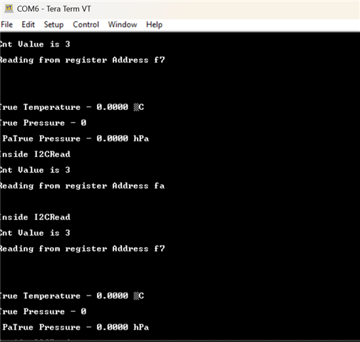
UARTprintf("True Temperature - %d.%04d °C",tempInt1,tempInt2);
/* API is used to read the true pressure*/
/* Input value as uncompensated pressure*/
v_actual_press_u32 = bmp280_compensate_pressure_int32(v_data_uncomp_pres_s32);
pres = ((int)v_actual_press_u32)*0.01;
presInt1 = pres;
presFrac = pres - presInt1; // Get fraction (0.0123).
presInt2 = presFrac * 10000;
UARTprintf("\n");
UARTprintf("True Pressure - %d\n Pa",v_actual_press_u32);
UARTprintf("True Pressure - %d.%04d hPa",presInt1,presInt2);
UARTprintf("\n");
SysCtlDelay(2*g_ui32SysClock/3);
}
}
#ifdef BMP280_API
/*--------------------------------------------------------------------------*
* The following function is used to map the I2C bus read, write, delay and
* device address with global structure bmp280_t
*-------------------------------------------------------------------------*/
s8 I2C_routine(void) {
/*--------------------------------------------------------------------------*
* By using bmp280 the following structure parameter can be accessed
* Bus write function pointer: BMP280_WR_FUNC_PTR
* Bus read function pointer: BMP280_RD_FUNC_PTR
* Delay function pointer: delay_msec
* I2C address: dev_addr
*--------------------------------------------------------------------------*/
bmp280.bus_write = BMP280_I2C_bus_write;
bmp280.bus_read = BMP280_I2C_bus_read;
bmp280.dev_addr = BMP280_I2C_ADDRESS2;
bmp280.delay_msec = BMP280_delay_msek;
UARTprintf("I2C_routine completed \n");
return BMP280_INIT_VALUE;
}
/************** I2C/SPI buffer length ******/
#define I2C_BUFFER_LEN 48
#define SPI_BUFFER_LEN 5
#define BUFFER_LENGTH 0xFF
#define BMP280_DATA_INDEX 1
#define BMP280_ADDRESS_INDEX 2
/*-------------------------------------------------------------------*
* This is a sample code for read and write the data by using I2C/SPI
* Use either I2C or SPI based on your need
* The device address defined in the bmp180.c
*
*-----------------------------------------------------------------------*/
/* \Brief: The function is used as I2C bus write
* \Return : Status of the I2C write
* \param dev_addr : The device address of the sensor
* \param reg_addr : Address of the first register, where data is to be written
* \param reg_data : It is a value held in the array,
* which is written in the register
* \param cnt : The no of bytes of data to be written
*/
s8 BMP280_I2C_bus_write(u8 dev_addr, u8 reg_addr, u8 *reg_data, u8 cnt)
{
s32 iError = BMP280_INIT_VALUE;
u8 array[SPI_BUFFER_LEN];
u8 stringpos = BMP280_INIT_VALUE;
array[BMP280_INIT_VALUE] = reg_addr;
for (stringpos = BMP280_INIT_VALUE; stringpos < cnt; stringpos++) {
array[stringpos + BMP280_DATA_INDEX] = *(reg_data + stringpos);
}
if(1==I2CMWrite(&g_sI2CInst, dev_addr, array,cnt+1, BMP280AppCallback, &bmp280)){
iError = BMP280_INIT_VALUE;
SysCtlDelay(2);
}
else{
iError = BMP280_INIT_VALUE-1;
SysCtlDelay(2);
}
/*
* Please take the below function as your reference for
* write the data using I2C communication
* "IERROR = I2C_WRITE_STRING(DEV_ADDR, ARRAY, CNT+1)"
* add your I2C write function here
* iError is an return value of I2C read function
* Please select your valid return value
* In the driver SUCCESS defined as BMP280_INIT_VALUE
* and FAILURE defined as -1
* Note :
* This is a full duplex operation,
* The first read data is discarded, for that extra write operation
* have to be initiated.Thus cnt+1 operation done in the I2C write string function
* For more information please refer data sheet SPI communication:
*/
return (s8)iError;
}
/* \Brief: The function is used as I2C bus read
* \Return : Status of the I2C read
* \param dev_addr : The device address of the sensor
* \param reg_addr : Address of the first register, where data is going to be read
* \param reg_data : This is the data read from the sensor, which is held in an array
* \param cnt : The no of data to be read
*/
s8 BMP280_I2C_bus_read(u8 dev_addr, u8 reg_addr, u8 *reg_data, u8 cnt)
{
s32 iError = BMP280_INIT_VALUE;
u8 array[SPI_BUFFER_LEN] = {BMP280_INIT_VALUE};
u8 stringpos = BMP280_INIT_VALUE;
array[BMP280_INIT_VALUE] = reg_addr;
UARTprintf("Inside I2CRead\n");
UARTprintf("Cnt Value is %d\n",cnt);
UARTprintf("Reading from register Address %x \n",array[0]);
/* Please take the below function as your reference
* to read the data using I2C communication
* add your I2C read function here.
* "IERROR = I2C_WRITE_READ_STRING(DEV_ADDR, ARRAY, ARRAY, 1, CNT)"
* iError is an return value of SPI write function
* Please select your valid return value
* In the driver SUCCESS defined as BMP280_INIT_VALUE
* and FAILURE defined as -1
*/
if(1==I2CMRead(&g_sI2CInst, dev_addr, array, 1, array, cnt, BMP280AppCallback, &bmp280)){
iError = BMP280_INIT_VALUE;
SysCtlDelay(g_ui32SysClock/(3*1000));
}
else{
iError = BMP280_INIT_VALUE-1;
SysCtlDelay(2);
}
for (stringpos = BMP280_INIT_VALUE; stringpos < cnt; stringpos++) {
// UARTprintf("Read data from I2C device is %x \n",array[stringpos]);
*(reg_data + stringpos) = array[stringpos];
}
SysCtlDelay(3);
UARTprintf("\n");
return (s8)iError;
}
/* Brief : The delay routine
* \param : delay in ms
*/
void BMP280_delay_msek(u32 msek)
{
/*Here you can write your own delay routine*/
//
// Delay for 1 millisecond. Each SysCtlDelay is about 3 clocks.
//This is not most efficient was for a delay function but serves the purpose here.
SysCtlDelay((g_ui32SysClock / (1000 * 3))*msek);
}
#endif
This the output