This thread has been locked.

If you have a related question, please click the "Ask a related question" button in the top right corner. The newly created question will be automatically linked to this question.

AM2432: custom flash support with IS25LP256D

Part Number: AM2432
Other Parts Discussed in Thread: UNIFLASH, SYSCONFIG, LP-AM243, AM2434

Tool/software:

Hi,

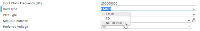
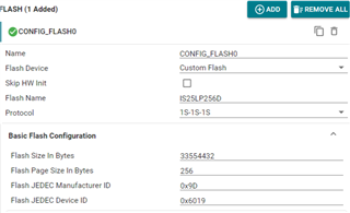
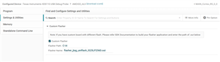
We have one custom board with AM2432 ALV chip and The Flash we select is IS25LP256D and in QSPI mode. Now we want to flash some hello world image into the board as bring up. 

Below are steps I have done:

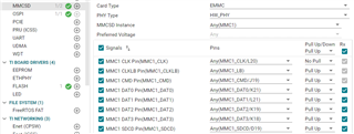
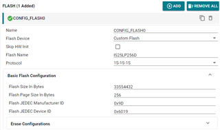
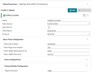
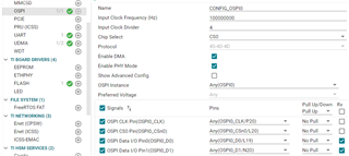
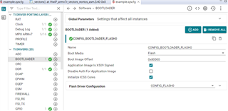
 1. Follow AM243x MCU+ SDK: Adding Support For a Custom Flash Device (ti.com) , get the SDFM paramenters and save it into .json file .

----------------------------------------------------------------------------------------

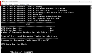
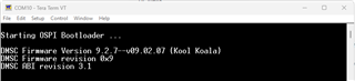
Starting SOC Initialization ...

Resetting self cluster ...

[OSPI Flash Diagnostic Test] Starting ...

[OSPI Flash Diagnostic Test] Flash Manufacturer ID : 0x9D

[OSPI Flash Diagnostic Test] Flash Device ID       : 0x6019

[OSPI Flash Diagnostic Test] Executing Flash Erase on first block...

[OSPI Flash Diagnostic Test] Done !!!

[OSPI Flash Diagnostic Test] Performing Write-Read Test...

[OSPI Flash Diagnostic Test] Write-Read Test Passed!

[QSPI Flash Diagnostic Test] SFDP Information :

================================================

                      SFDP                     

================================================

SFDP Major Revision                       : 0x1

SFDP Minor Revision                       : 0x6

Number of Parameter Headers in this Table : 2


Types of Additional Parameter Tables in this flash

---------------------------------------------------

Unsupported Parameter Table type!!! - 0x29D


JSON Data for the flash :
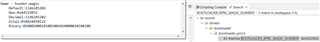
 

{


"flashSize": 33554432,

"flashPageSize": 256,

"flashManfId": "0x9D",

"flashDeviceId": "0x6019",

"flashBlockSize": 65536,

"flashSectorSize": 4096,

"cmdBlockErase3B": "0xD8",

"cmdBlockErase4B": "0xD8",

"cmdSectorErase3B": "0x20",

"cmdSectorErase4B": "0x20",

"protos": {

"p111": {

"isDtr": false,

"cmdRd": "0x03",

"cmdWr": "0x02",

"modeClksCmd": 0,

"modeClksRd": 0,

"dummyClksCmd": 0,

"dummyClksRd": 0,

"enableType": "0",

"enableSeq": "0x00",

"dummyCfg": null,

"protoCfg": null,

"strDtrCfg": null

},

"p112": {

"isDtr": false,

"cmdRd": "0x3B",

"cmdWr": "0x02",

"modeClksCmd": 0,

"modeClksRd": 0,

"dummyClksCmd": 0,

"dummyClksRd": 8,

"enableType": "0",

"enableSeq": "0x00",

"dummyCfg": null,

"protoCfg": null,

"strDtrCfg": null

},

"p114": {

"isDtr": false,

"cmdRd": "0x6B",

"cmdWr": "0x02",

"modeClksCmd": 0,

"modeClksRd": 0,

"dummyClksCmd": 0,

"dummyClksRd": 8,

"enableType": "2",

"enableSeq": "0x00",

"dummyCfg": null,

"protoCfg": null,

"strDtrCfg": null

},

"p118": null,

"p444s": {

"isDtr": false,

"cmdRd": "0xEB",

"cmdWr": "0x02",

"modeClksCmd": 0,

"modeClksRd": 2,

"dummyClksCmd": 0,

"dummyClksRd": 4,

"enableType": "2",

"enableSeq": "0x04",

"dummyCfg": {

"isAddrReg": false,

"cmdRegRd":"0x00",

"cmdRegWr":"0x00",

"cfgReg":"0x00000000",

"shift":0,

"mask":"0x00",

"bitP":0

},

"protoCfg": {

"isAddrReg": false,

"cmdRegRd": "0x00",

"cmdRegWr": "0x00",

"cfgReg": "0x00000000",

"shift": 0,

"mask": "0x00",

"bitP": 0

},

"strDtrCfg": {

"isAddrReg": false,

"cmdRegRd": "0x00",

"cmdRegWr": "0x00",

"cfgReg": "0x00000000",

"shift": 0,

"mask": "0x00",

"bitP": 0

}

},

"p444d": {

"isDtr": false,

"cmdRd": "0xEB",

"cmdWr": "0x02",

"modeClksCmd": 0,

"modeClksRd": 2,

"dummyClksCmd": 0,

"dummyClksRd": 4,

"enableType": "2",

"enableSeq": "0x04",

"dummyCfg": {

"isAddrReg": false,

"cmdRegRd":"0x00",

"cmdRegWr":"0x00",

"cfgReg":"0x00000000",

"shift":0,

"mask":"0x00",

"bitP":0

},

"protoCfg": {

"isAddrReg": false,

"cmdRegRd": "0x00",

"cmdRegWr": "0x00",

"cfgReg": "0x00000000",

"shift": 0,

"mask": "0x00",

"bitP": 0

},

"strDtrCfg": {

"isAddrReg": false,

"cmdRegRd": "0x00",

"cmdRegWr": "0x00",

"cfgReg": "0x00000000",

"shift": 0,

"mask": "0x00",

"bitP": 0

}

},

"p888s": null,

"p888d": null,

"pCustom": {

"fxn": null

}

},

"addrByteSupport": "0",

"fourByteAddrEnSeq": "0xA9",

"cmdExtType": "NONE",

"resetType": "0x30",

"deviceBusyType": "1",

"cmdWren": "0x06",

"cmdRdsr": "0x05",

"srWip":  0,

"srWel":  1,

"cmdChipErase": "0xC7",

"rdIdSettings": {

"cmd": "0x9F",

"numBytes": 5,

"dummy4": 0,

"dummy8": 0

},

"xspiWipRdCmd": "0x00",

"xspiWipReg": "0x00000000",

"xspiWipBit": 0,

"flashDeviceBusyTimeout": 60000000,

"flashPageProgTimeout": 200

}


All tests have passed!!

----------------------------------------------------

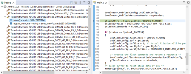
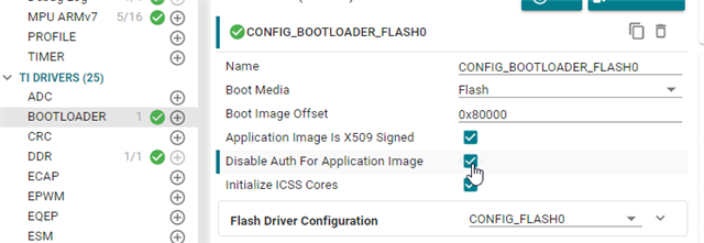
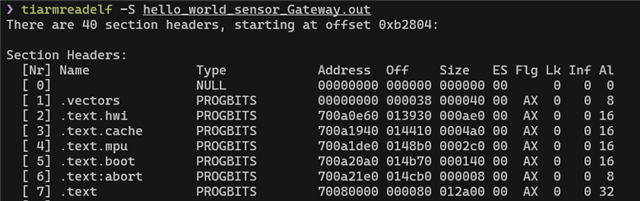
2. modify the flasher_jtag_uniflash_AM243EVM demo and get the .out file

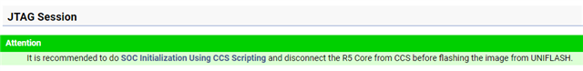
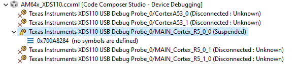
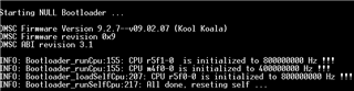
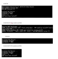
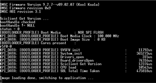
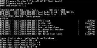
3.  Initialize the SOC with JScript again.
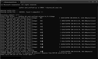
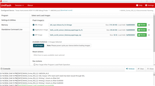
4. Setup Uniflash

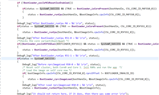
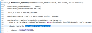
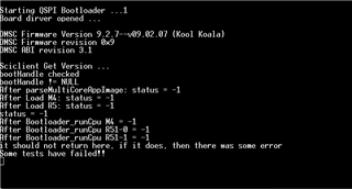
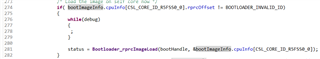
5. Load Image and error happened

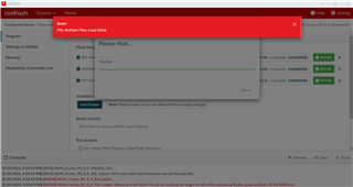
Any idea how to continue?

Thank you in advance.

  • Hello,

    Instead of JTAG_UNIFLASH, could you please integrate the custom flash with SBL_UART_UNIFLASH

    https://software-dl.ti.com/mcu-plus-sdk/esd/AM243X/latest/exports/docs/api_guide_am243x/TOOLS_FLASH.html#TOOLS_FLASH_UART_UNIFLASH

    Once you have this working, we can checkout the JTAG one.

    Regards,

    Prashant

  • Hi,

    All 7 UART ports are connected to RS485 transceiver on our board. We are now using UART6 (0 to 6) as DEBUG_LOG_PORT.

    We modified the sysconfig and add one GPIO to control the UART7_TX_EN. After this modification, we can get UART output on the PC through a RS485=>USB converter. 

    I can do the same modification to SBL_UART_UNIFLASH and come back.

    Thank you for the suggestion.

    BR

    Junjie

  • One more information is that we did not see any output from UART6 after we set the boot mode to UART mode. Should we see some output as described in the guidance?

  • Hello,

    In the UART bootmode, the ROM always uses UART0 to dump that string and also to receive the image. I am not sure about your UART setup but yes you must first see that string before trying out the SBL_UART_UNIFLASH.

    About the JTAG_FLASHER, is it your first time trying out this tool or it was working before but got the error now?

    Regards,

    Prashant

  • Hi,

    I also find that only UART0 can be used and a quick test is that there is no output on UART0.

    I will try to use UART0 to transfer image tomorrow.

    About the JTAG_FLASH, this is the first time I try with our custom board. We have succeeded to use UNIFLASH to program image into AM243-EVM and LP-AM243 board. 

    BR

    Junjie

  • Hello,

    About the JTAG_FLASH, this is the first time I try with our custom board. We have succeeded to use UNIFLASH to program image into AM243-EVM and LP-AM243 board. 

    In that case, I think you are already familiar with this flashing procedure. But, just in case, have you made sure you are initializing the SoC before clicking on "Load Images" button to start the flashing procedure?

    This is mentioned in the following doc

    https://software-dl.ti.com/mcu-plus-sdk/esd/AM243X/09_02_00_50/exports/docs/api_guide_am243x/TI_UNIFLASH_TOOL.html

    Regards,

    Prashant

  • Hi,

     "initializing the SoC" is done before I load the image. One question here is that I rebuild the JTAG_Flasher.out based on the example project of EVM board (AM2434 ALV). Our board is based on AM2432 ALV.  Will this difference cause some issue during JTAG flash?

    Regarding the UART_UNIFLASH. After we force the RS485_EN to be High, we can get the print from UART0. Then We force the RS485_EN to be low, and start the uart_flash operation, It stucks at transmitting the  sbl_uart_uniflash.Debug.hs_fs.tiimage

    Any idea?

    Thank you advance.

    BR

    Junjie

  • Hello,

    One question here is that I rebuild the JTAG_Flasher.out based on the example project of EVM board (AM2434 ALV). Our board is based on AM2432 ALV.  Will this difference cause some issue during JTAG flash?

    This should not cause any issue. The JTAG flasher only runs on R5FSS0-0 core and does not use any other core.

    It maybe the case that the JTAG flasher boots but fails somewhere probably in the OSPI initialization and so the Uniflash times out waiting for a response. Can you manually connect to the core after the Uniflash reports failure and see what address the core is suspended at?

    Regarding the UART_UNIFLASH. After we force the RS485_EN to be High, we can get the print from UART0.

    Do you mean you are getting some hex string on the UART0? If so, you could try booting the SBL NULL directly over UART and see if that works.

    https://e2e.ti.com/support/processors-group/processors/f/processors-forum/1329012/am6442-sbl-is-blocked-in-an-loop-of-bootloader_socwaitforfwboot/5057360#5057360

    Regards,

    Prashant

  • Hi,

    We can get connect to UART0 now (after work on another board). There is some HW issue on Previous board.

    But still we can not load the image over UART0. any idea?

    It always report expeted ACK; got b'C' for block 1

    BR

    Junjie

  • Hi Prashant

    >>This should not cause any issue. The JTAG flasher only runs on R5FSS0-0 core and does not use any other core.

    >>It maybe the case that the JTAG flasher boots but fails somewhere probably in the OSPI initialization and so the Uniflash times out waiting for a response. Can you manually connect to the core after the Uniflash reports failure and see what address the core is suspended at?

    Can you elaborate how to see the address MCU get suspended at? If uniflash report error, seems the Ccs is disconnected.

    Regards

    Zekun

  • Hi,

    But still we can not load the image over UART0. any idea?

    It looks the SoC is getting reset in the middle of the procedure. Have you tried multiple times and see the same issue? Please make sure you are starting the flashing procedure as soon as the board is powered on in the UART bootmode.

    Can you elaborate how to see the address MCU get suspended at? If uniflash report error, seems the Ccs is disconnected.

    After the Uniflash failure, CCS can be used to connect to the R5FSS0-0 core. Once connected, it will be suspended at some address like the following

    Regards,

    Prashant

  • Hi,

    We suspend at 0x00000044

  • Hi,

    We did some more tests on JTAG UNIFLASH.

    1. We removed the IS25LP256D on our custom board.

    2. solid the flash chip (removed from AM243-LP board) onto our custom board.

    3. Intialize SOC steps

    4. Use Uniflash to flash the board with TI AM243-LP configuration.

    5. Uniflash report Successfully. 

    So it seems that all related HW part is ok, the issue is in the flasher_jtag_uniflash.out I generated according to your manual.

    And regarding the UART_UNIFLASH, the issue is in uart communication itself, we can look into it later.

    Shall we focus on JTAG_UNIFLASH?

    BR

    Junjie

  • Hi Junjie,

    Yes, we should focus on JTAG flasher.

    Let's forget Uniflash for now. Once we have confirmed the JTAG flasher is booting and compatible with your custom flash part, we can use Uniflash then. So, the idea is instead of letting Uniflash load JTAG flasher out file, we will do it manually using CCS.

    So, after the SoC initialization, you could reset the core and load the JTAG flasher out file using "Load Program" option. This should boot the application. Then check how far it is going successfully. Without any changes, it should ideally fail at Board_driversOpen.

    Then, you can repeatedly update the flash configurations until the Board_driversOpen returns SUCCESS.

    The debugging should look something like something like the followingh

    Afterwards, you should be able to use it successfully with Uniflash.

    Regards,

    Prashant

  • Hi Prashant,

    I found the issue this morning.

    There are two reasons:

    1. there is a default MMC configuration in the example sysconfig. While we don't have MMC device on our board. It stuck at the open mmc function.

    But I can not remove the configuration of MMC, otherwise it will report build errors. Any idea why?

    2. The sysconfig will only input the values according to the protocol selected. The default config is 8-8-8, so it load the wrong paramenters. After I switch to 1s-1s-1s, I have to load the json file again.

    Now the JTAG_UNIFLASH reports successfully.

    What I programed is 

    1. Modified ospi_sbl, which I have modified the qspi flash part as Jtag_uniflash.out, enable uart 7 for debug port.

    2. Modified hello world app, enabled UART7 for debug port. (Which I can see output from UART7 in debug mode.)

    But After we switch back to QSPI mode, there is no output.

    Any suggestion how to boot up a hello world app?


    Thank you.

    BR

    Junjie

  • Hi Junjie,

    But I can not remove the configuration of MMC, otherwise it will report build errors. Any idea why?

    To disable the initialization of eMMC, you just need to set Card Type to NO_DEVICE.

    Any suggestion how to boot up a hello world app?

    Can you first try flashing and booting the SBL NULL image? If this boots then this will atleast confirm the JTAG flasher is working correctly. We can then move to SBL OSPI and Hello World.

    Regards,

    Prashant

  • Hi Prashant,

    I modified the JTAG_UNIFLAH as follow configuration 1s-1s-1s.

    I modify the uart part to use uart6 in sbl_null example project and generated the file.

    After I programmed the board,

    1. I switch the board back to SPI mode with mode 0 and  CS0. BOOT pin is (LSB first :110 (PLL 25MHZ) 1100 (SPI) 00 (MODE 0 AND CS0)

    2. I switch the board back to QSPI mode with lclk 0 and  CS0. BOOT pin is (LSB first :110 (PLL 25MHZ) 0100 (QSPI) 00 (lclk = 0 AND CS0)

    There is no output.

    Any idea? 

    Change protocol to 4s-4s-4s? or 1s-1s-4s? and use QSPI mode?

    BR

    Junjie

  • Hi Junjie,

    After I programmed the board,

    Does the JTAG Uniflash report that the flashing is done successfully?

    If it does then we can assume it has correctly written the image in flash and so should focus on ROM booting from SPI. In this case, there are two possibilities here:

    1. The ROM did boot the SBL NULL image but the UART logging might not be working.
    2. The ROM failed to boot from SPI probably because of incorrect bootmode.

    To identify which one it is, could you please connect to the R5F core with JTAG and see the address the core is suspended at. If it is 0x00000044 then it's the first case. If it is 0x41xxxxxx then it's the second case.

    For the first case, you would have to set the correct UART settings in the SBL NULL example.

    For the second case, you could try the xSPI bootmode with SFDP disabled (B0-B7: 11001110, B8-B15: 00000000).

    Regards,

    Prashant

  • Hi Prashant,

    Thank you for the feedback. I just tried to set the JTAG_UNIFLASH to 4s-4s-4s mode and generated a new JTAG_UNIFLASH_444.out .

    After programming the SBL_NULL to flash with this  JTAG_UNIFLASH_444.out. With QSPI mode (B0-B7: 11001000), I can boot up the SBL_NULL and see the print!

    Then I imported a sbl_ospi example and modified the sysconfig same as JTAG_UNIFLASH_444.out

    It seems stuck at some place.

    Is there some way to debug this sbl_ospi except adding some debug_log?

    Another guess is that maybe I need to modify some config from ospi to qspi?

    I checked the difference between sbl_ospi lp and EVM. sbl_ospi use 4s-4d-4d and enabled PHY and DMA

    Any idea?

    Thank you.

    BR

    Junjie

  • Hi Junjie,

    Do you not have DMA and PHY enabled in your SBL OSPI? If you do not, can you try enabling them and see if that works?

  • No, I started from the EVM sbl_ospi demo. I can try it now and also try 4s-4d-4d.

  • Hi Prashant,

    I did a few tests, please see below summary.

    And another thing is that I tried to flash the board with 4S-4D-4D mode and generated a new JTAG_UNIFLASH_444d.out . The Uniflash report errors at the last step that verify error. So it seems only 4S-4S-4S can work.

    BR

    Junjie

  • Hello,

    In 4s-4s-4s mode with PHY and DMA enabled, can you please disable the authentication with the following check in the SBL OSPI sysconfig and try booting?

    Regards,

    Prashant

  • Hi,

    It is already disabled.

    BR

    Junjie

  • It is already disabled.

    No, the authentication is currenly enabled. You would need to check the box corresponding to "Disable auth for Appimage Image" to skip authentication.

  • Hi,

    After "Disable auth for Appimage Image", it seems better, but still it stuck before running Hello world app.

    The Hello world app I have tested with debug mode. it can print out Hello world.

    Any suggestion?

    BR

    Junjie

  • Hello,

    I am thinking the SBL OSPI isn't yet compatible with your custom part. So, it might be reading incorrect data leading to the issue.

    Can you please run the OSPI_FLASH_IO example via CCS after initializing the SoC with SBL NULL or any other method? If this example runs successfully then copy paste the exact flash configurations to SBL OSPI and then see if the Hello World boots?

    https://software-dl.ti.com/mcu-plus-sdk/esd/AM243X/09_02_00_50/exports/docs/api_guide_am243x/EXAMPLES_DRIVERS_OSPI_FLASH_IO.html

    Regards,

    Prashant

  • Hi,

    I tried to modify the OSPI_FLASH_IO example, it can pass all tests.

    Then I copied the same configuration to my SBL_OSPI project and add some print. 

    console output is that "After Load rprcImageLoad R50-0 = -1"

    Then I traced the code it seems the magic number doesn't match. Any suggestion?

    And another thing is that it can only boot up once after I programmed the image. Then it will enter a mode like NO_BOOT? same current as DEV mode, but I can not run the Initialize_SOC steps. I assume that the primary boot mode qspi failed and it enters the backup boot mode or it corrupts the flash? Then we can no longer program the flash until we change the primary boot mode back to DEV. It takes time to change this mode, is there some other way to recover without change the boot mode pins?

    BR

    Junjie

  • Hello,

    Then I traced the code it seems the magic number doesn't match. Any suggestion?

    Can you please check the value of "cpuInfo->rprcOffset"? Either the SBL OSPI reading data from the incorrect offset or reading incorrect data from the correct offset.

    And another thing is that it can only boot up once after I programmed the image.

    Do you mean to say once you program the SBL OSPI and Hello World appimage and change the bootmode to QSPI the SBL OSPI boots but it does not boot again after a Powering Off/On the board?

    Regards,

    Prashant

  • Can you please check the value of "cpuInfo->rprcOffset"? Either the SBL OSPI reading data from the incorrect offset or reading incorrect data from the correct offset.

    It is 0x20

    Do you mean to say once you program the SBL OSPI and Hello World appimage and change the bootmode to QSPI the SBL OSPI boots but it does not boot again after a Powering Off/On the board?

    Yes, this is the case.

    I checked another post that mentioning the device tyep. according to the printout info, we are fs type.

    [FAQ] TDA4VM: J72E : How to determine if this is a GP or HS device - Processors forum - Processors - TI E2E support forums

    Below is our console output

    02000000011a0000616d3634780000000000000048534653000002000000020002a6000000000000b018658ad99dc903c8c9bfb27b12751099920a042ad1dfea7b7ba57369f15546de285edde6a7b39a8bdc40a27b237f8fb1e57f245e80b929c1e28b024aa2ecc6ad0bc40b0000000000000000000000000000000000000000000000000000000000000000000000000000000000000000000000000000000000000000000000005f2af3785f7cefef23f0d67f8aa0e217ddfb4b26e8fc9d19ed7c5a8b1a27adea

    Below is what I parsed by using the tool described in below links.

    3.3.1. GP to HS-FS Migration Guide — Processor SDK AM64X Documentation 

    Below is what I copied from the makefile_ccs_bootimage_gen

    ifeq ($(ENC_SBL_ENABLED),yes)
    $(BOOTIMAGE_CERT_GEN_CMD) --swrv 1 --sbl-enc --enc-key $(APP_ENCRYPTION_KEY) --sbl-bin $(BOOTIMAGE_BIN_NAME) --sysfw-bin $(SYSFW_PATH)/sysfw-hs-enc.bin --sysfw-inner-cert $(SYSFW_PATH)/sysfw-hs-enc-cert.bin --boardcfg-blob $(BOARDCFG_BLOB) --sbl-loadaddr $(SBL_RUN_ADDRESS) --sysfw-loadaddr $(SYSFW_LOAD_ADDR) --bcfg-loadaddr $(BOARDCFG_LOAD_ADDR) --key $(BOOTIMAGE_CERT_KEY) --debug DBG_FULL_ENABLE --rom-image $(BOOTIMAGE_NAME)
    else
    $(BOOTIMAGE_CERT_GEN_CMD) --swrv 1 --sbl-bin $(BOOTIMAGE_BIN_NAME) --sysfw-bin $(SYSFW_PATH)/sysfw-hs-enc.bin --sysfw-inner-cert $(SYSFW_PATH)/sysfw-hs-enc-cert.bin --boardcfg-blob $(BOARDCFG_BLOB) --sbl-loadaddr $(SBL_RUN_ADDRESS) --sysfw-loadaddr $(SYSFW_LOAD_ADDR) --bcfg-loadaddr $(BOARDCFG_LOAD_ADDR) --key $(BOOTIMAGE_CERT_KEY) --debug DBG_FULL_ENABLE --rom-image $(BOOTIMAGE_NAME)
    endif

    Any suggestion?

    BR

    Junjie

  • Hi,

    Should we focus on this auth for app image?

    If i enable this option, it will return -1 at above place.

    If I disable this option, where to turn off this encryption of application image?

    BR

    Junjie

  • Hi,

    Some update:

    I do one more test on the board that  we replaced the FLASH with the one on LP board (S25HL512T).

    With the same configuration as sbl_ospi_am243_lp, we can boot up the SBL without any error, but still threre is no hello world print.

    The difference between Custom flash (IS25lp256d) and S25HL512T is load rprc step. With custom flash it failed, with TI default flash, it report 0.

    But neither of them can boot up hello world.

    Could you give some feedback on how to continue?

    BR

    Junjie

  • Hi Prashant

    Could you prioritize this issue because it has pending for 2 weeks. I will on site support this the day after tomorrow, do you have any ideas we can test? 

    Regards

    Zekun

  • Hello,

    Could you give some feedback on how to continue?

    You would need to connect to the R5F core and note down the address the core is suspended at. If the address is in the regions used by Hello World application that means the application did boot but did not dump logs on UART for some reasons.

    If you can share the Hello World application image, I can also check it once on my side.

    Regards,

    Prashant

  • Hi Prashant

    Yes we can share the application. 

    But if we use customer’s flash, it will failed at rprc load. What is next step to debug this with customer flash?

    Regards

    Zekun

  • Please find the hello world application.

    Some modification on use UART6 as debug uart port. and set pin P17 as GPIO output with default high.

    3348.Debug.zip

    With TI flash, it still stuck at sbl address.

    BR

    Junjie

  • With TI flash, it still stuck at sbl address.

    That is not the SBL address. The address lies in the MSRAM 3rd Bank which if not changed is used for R5F_0 applications

    This indeed is the case

    So, this means the Hello World application is indeed booting but either the UART logging is not working or the application at run time is getting into some trouble.

    The way to debug what's going wrong with the Hello World image is to put an infinite loop at the very start of its main function and then boot it as usual. Once booted, the control will be trapped inside the forever loop. Then connect to the core, load the symbols, break the infinite loop and debug it step by step.

    Regards,

    Prashant

  • Hi,

    With the same setup, I can not run the TI flash after I reprogrammed the flash. I will try your suggestion later.

    Any suggestion on why it fails on custom flash? If we can also reach the same step (pass load rprc without error) on Custom flash, I can try on it also.

    BR

    Junjie

  • Hi Prashant,

    With TI chip, we try to debug the magic number, we add while loop in below position.

    And got the magic number has one bit error.

    On IS25LP256D, same magic number error, but different number

    Any idea?

    BR

    Junjie

  • Hello,

    And got the magic number has one bit error.

    What is changed now that you are getting this mismatch even for the flash part on TI EVM?

    You previously mentioned that the loadrprc did not report any failure for the flash part on TI EVM and the application was at least indeed booting?

    One other thing, the SBL_OSPI from AM243x-EVM includes flashFixUpOspiBoot function call for the OSPI flash part. Since, you are using the QSPI, have you already removed this function call?

    Regards,

    Prashant

  • Hi, 

    What is changed now that you are getting this mismatch even for the flash part on TI EVM?

    You previously mentioned that the loadrprc did not report any failure for the flash part on TI EVM and the application was at least indeed booting?

    Not from TI EVM, I use the flash chip on TI AM243-LP board. I have not change anything, maybe we fly wire and the signal is not stable, but now it can never go to that state.

    One other thing, the SBL_OSPI from AM243x-EVM includes flashFixUpOspiBoot function call for the OSPI flash part. Since, you are using the QSPI, have you already removed this function call?

    I have commented it just now and had a try. same magic number error.

    BR

    Junjie

  • Hi Prashant and Zequn,

    Thank you for your support. Now I found one workaround to boot up a hello world app.

    Remaining issue:

    1.  we have to disable Auth for the application image, otherwise it will report some tests fails.

    2. I didn't find where to enable the dac mode in Sysconfig, so I have to modify the default value in ospi_am243x.syscfg.js as a work around.

    The root cause is there is a bug in Bootloader_verifyMulticoreImage->Bootloader_getMsgLen-> Bootloader_findSeq

    It does not check if the dac mode is enabled or not, directly use pointer to access the flash address 0x60008000. which cause the the system stuck just after BOOT_Handler != NULL. (in Bootloader_verifyMulticoreImage)

    While the correct way should be like the same as what the drivers does in OSPI_readDirct to enable DAC first.

    The summary is as follow:

    1. build and run the flash_diag_example, read SDFM parameters into xxx.json

    2. Modify the sysconfig in Flasher_jtag_uniflash example

        - In OSPI section, change input CLK to be 100000000 (100M)

        - In Flash section, Set protocol to be 1s-1s-1s

        -load the flash parameter from json file got in step 1

        - in MMCSD section, select NO_DEVICE as our board has no SD card.

        - Build project

    3. Modify the sysconfig in sbl_ospi example

        - In OSPI section, change input CLK to be 100000000 (100M)

        - In Flash section, Set protocol to be 1s-1s-1s

        -load the flash parameter from json file got in step 1.

        - in Bootloader section, select "Disable auth for Application Image"

        - modify the ospi_am243x.syscfg.js in SDK_PATH/source/drivers/.meta/ospi/soc to enable dac.

        - Build project

    BR

    Junjie

  • Hi Junjie,

    The root cause is there is a bug in Bootloader_verifyMulticoreImage->Bootloader_getMsgLen-> Bootloader_findSeq

    This is a known issue expected to be fixed in the next release

    https://e2e.ti.com/support/microcontrollers/arm-based-microcontrollers-group/arm-based-microcontrollers/f/arm-based-microcontrollers-forum/1332543/mcu-plus-sdk-am243x-ospi-multi-partition-bootloader-example-not-working/5079592#5079592

    Regards,

    Prashant