This thread has been locked.

If you have a related question, please click the "Ask a related question" button in the top right corner. The newly created question will be automatically linked to this question.

MSPM0G3507: CAN TX Example Question

Part Number: MSPM0G3507
Other Parts Discussed in Thread: , TCAN1046ADEVM

Tool/software:

I am currently using the MSPM0G3507 development board and working with examples from the mspm0_sdk_1_30_00_03. I am using the mcan_single_message_tx and mcan_multi_message_tx examples. I tried to observe the transmitted waveform by connecting an oscilloscope to the TX and GND pins. However, no matter how I try, there is no waveform transmitted on the TX pin.

Could you please tell me what I need to change? Thank you.

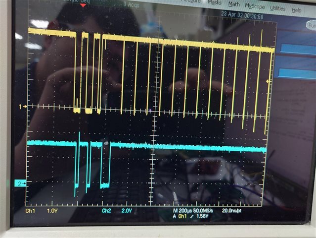
I have set two variables in the program to check if it enters the interrupt and if the program finishes. Everything seems to be working fine, but there is still no signal generated. What might be the issue? Neither of the examples produce a TX signal. The first time I flash and run the program (pressing PB21), I receive a strange error waveform. However, no matter how I test it afterward (pressing PB21), there is no activity on the TX pin. The oscilloscope shows the signal remains at a high level with no changes.

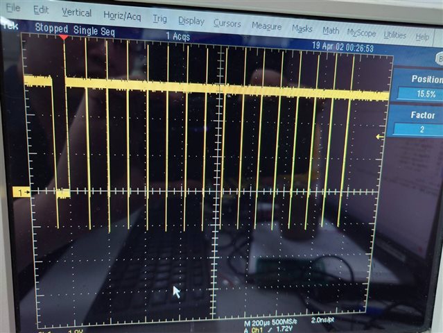
The image above shows the signal generated the first time I press (PB21) after flashing the code (the signal content does not match the transmitted data). However, no matter how I test it afterward, the TX pin does not produce any signal and remains at a high level.

Thank you.

  • Hello FENG,

    You need another device to receive the data to complete the transmission. Just using one to send the data but no device receiving data can't let you see the correct data transmission.

    1), You can choose to use another LaunchPad (download the mcan_single_message_rx and mcan_multi_message_rx ) to receive the data, and observe the data transmission using oscilloscope.

    2). You can choose to use a CAN transceiver to receive the data. And if you choose to use the CAN transceiver, you can refer to this e2e post.

    (33) MSPM0G3507: CAN - Arm-based microcontrollers forum - Arm-based microcontrollers - TI E2E support forums

    Best Regards,

    Janz Bai

  • Hello Janz Bai,

    Thank you for your response. I will follow your advice and use two boards for CAN communication.

    Now I have a question. In the example, I did not see the mcan_single_message_rx and mcan_multi_message_rx that you mentioned.

    In my example, the CAN_RX part only has mcan_message_rx and mcan_message_rx_tcan114x.

    Can these two examples also be used as my RX functionality code? Will they ensure my CAN communication works properly? Thank you.

  • Hello FENG,

    1). You can use the mcan_message_rx directly, this can be used as your RX functionality code. You can use "mcan_single_message_tx" & "mcan_message_rx" or use "mcan_multi_message_tx" & "mcan_message_rx".

    2). You can read the "Readme" and read the code to know the specific usage of the example code.

    3). The "mcan_message_rx_tcan114x" can be used when you use the tcan114x in your CAN network.

    4). When you use the example code or any other CAN code, you should check and ensure that the "Arbitration Bit Rate" parameters of CAN transmitter and CAN receiver are the same, and ensure that the "Data Bit Rate" parameters of CAN transmitter and CAN receiver are the same. 

    Best Regards,

    Janz Bai

  • Hello Janz Bai,

    I followed your advice and used two boards for communication. Both of my boards are MSPM0G3507. I used the programs `mcan_message_rx` and `mcan_multi_message_tx`, as well as `mcan_message_rx` and `mcan_single_message_tx`. I also paid attention to the Arbitration Bit Rate and Data Bit Rate, setting them the same on both boards.

    However, through my testing, I found that the CAN communication is not working. When I press PB21 (TX) for the first time, the RX board enters the interrupt, but the program does not execute successfully. The value of `gInterruptLine1Status` in the RX program is 0x09800000, so the program does not enter the if loop. When I press PB21 (TX) a second time, the RX board has no response and does not enter the interrupt.

    Could you advise me on what other settings I need to change? Also, where can I find the return values of the `DL_MCAN_getIntrStatus` function? Thank you.

    The yellow waveform represents TX transmission, and the blue waveform represents RX reception. The Arbitration Bit Rate and Data Bit Rate are set the same in both the TX and RX programs. Could you advise me on what other errors I might need to correct? Thank you.

  • Hello Janz Bai,
    I've tested and observed that the reason the `gInterruptLine1Status` value equals 0x09800000 is because the PEA, EW, and EP bits in the `CANFD0_MCAN_IR` register are set to 1.
    Among these, PEA indicates a protocol error in the arbitration phase.
    Additionally, the LEC in the `CANFD0_MCAN_PSR` shows 001, indicating a Stuff Error: more than 5 equal bits in a sequence have occurred in a part of a received message where this is not allowed, along with other errors (including EP, EW, DLEC).

    How can I fix this? It seems to be a configuration issue. I am currently using almost all the default settings provided by the example code without any modifications. How should I configure the parameters to enable normal CAN communication between the two boards?
    Thank you, and I appreciate your assistance.

  • Hi PENG,

    If you want to achieve the communication of CAN with two LP-MSPM0G3507, addition two CAN transceivers are needed for transfer RX/TX signal to differential signal. In CAN standard protocol, the CAN controller built in MCU need to monitor the status of CAN bus as it transfer bits to CAN bus. During arbitration phase, if the CAN bus status is not equal to the one it set, there will be error occurred and it will exit CAN transfer.

    So it is recommended to use CAN transceivers connected to CAN RX/TX pins (for example TI's TCAN1046ADEVM). 

    Regards,

    Pengfei

  • Hi, Pengfei Xie,

    So, what you mean is that if I want to use two MSPM0G3507 boards to communicate with each other using CAN, I must have two CAN transceivers first, right? Otherwise, CAN communication will not be successful?

    Is this what you mean? Thank you.

  • Hi PENG,

    Yes, I think so. The transceivers might be necessary for CAN communication.  Each node connected to CAN bus need a transceiver. For further information, you could refers to TRM of MSPM0G3507 CAN-FD part or CAN standard protocol. 

    Regards,

    Pengfei

  • Hi, Pengfei,

    Alright, I'm currently waiting for the materials (CAN transceiver) to arrive. I will test it once I receive them. Thank you for your response, much appreciated.

    Best regards.

  • Hi PENG,

    If you have any questions after you received CAN transceiver, you could leave message under this thread. And I will temporarily close this thread. 

    Thanks!

    Regards,

    Pengfei