This thread has been locked.

If you have a related question, please click the "Ask a related question" button in the top right corner. The newly created question will be automatically linked to this question.

LP-MSPM0L1306: SWDIO disable generates over-current in standby mode

Part Number: LP-MSPM0L1306
Other Parts Discussed in Thread: MSPM0L1306,

Tool/software:

Hi,

I need to use PA19 and PA20 pin of MSPM0L1306 so I disable the "Debug Enable On SWD Pins" option.

For a first step I leave this pins default configured as cleared GPIO output.

After programming I remove connection jumpers between the microcontrolor and the XDS110-ET debugging probe.

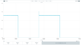
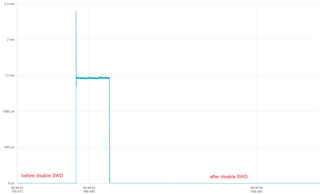
Everything seems to work well but when the processor goes into STANDBY0 mode I notice an over-consumption of current (>1mA instead of 4µA when the SWDIO are activated).

I tried different configurations (pins configured as GPIOinput, IOMUX cleared...) but nothing changes.

I also tried to disable Debug on SWD pins by software but it remains the same.

Is there something more to do to get SWD pin function disable and not have this drawn current ? 

Thanks for your help

  • You have to  put the microcontroller into standby mode correctly. This typically involves setting the appropriate power control registers. 

  • Hi,

    Can you share your code? I will check from my side

    Regards,

    Zoey

  • Hi Zain Nasir,
    Thanks you for your reply. 
    Is there a difference to go to standby Mode when SWDIO are disable or not ? 
    Because my app was correctly entering in standby mode before desabling this function.
    Regards
  • Hello Zoey,

    Thank you for your interest in my problem.

    Here is a very basic example of code which shows this excess current consumption by disabling the debug function on the SWDIO pins in the syscfg file.

    I'm measuring current on an LP-MSPM0L1306 board by inserting an ammeter between pins J101.5 and J101.6.

    The progam is loaded (not in debug) and jumper in SDWIO pins between the XDS110-ET debug probe and micro-controller are removed.

    The system toggles  between STANBYMODE0 (LED1 off) and RUN (LED1 on) each 3 seconds. 

    When  SWDIO function is enable mesured  current toggles between 4µA and 6.47mA.

    When SWDIO function is disable, mesured  current toggles between 1.08mA and 6.72mA.

    Hope this helps you find what's wrong.

    Best regards,

    Jean-Paul Lopes

    ForumTI.zip

  • Hi,

    I see the same phenomena whether SWD is enabled or disabled.

    I have just remove all the jumpers J101. Use power monitor to see the current.

    Here is the result:

    I think the odd result might lie in the test hardware environment.

    Regards,

    Zoey

  • Hi Zoey,

    Thank you for your attention.

    I'm sorry but I don't understand your answer.

    Have you recompiled the code with and without the SDWIO feature enabled to compare the two modes?

    My test hardware environment is very simple: an LP-MSPM0L1306 board and an ammeter connect as specified in the MSPM0L1306 LaunchPad Development Kit User Guide in Chapter 2.6.

    I deactivate all the functions integrated on the card such as the LEDs (except Led1 to distinguish on/off modes), the thermistor...
    As I have set the option to automatically configure unused pins as cleared output for low power, I don't see how the hardware environment can explain the differences in current consumption per CPU when the SWDIO pins are enabled or not.

    Regards,

  • Hi,

    Yes I just re-compiled the code with and without the SDWIO feature enabled to compare the two mode.

    I have also  written a new test code from my side to check the current. Please check E2E_SWDdisable.zip

    B.R.

    Zoey

  • Hi,

    I finally found what the problem is :

    To avoid excessive current consumption, I have to do a POR after programming.
    It appears that a lower reset level is performed after programming and some debug functions remain active.

    Thanks for your time helping me.

    Regards,

    Jean-Paul Lopes