This thread has been locked.

If you have a related question, please click the "Ask a related question" button in the top right corner. The newly created question will be automatically linked to this question.

MSPM0L1306: Internal clock output

Part Number: MSPM0L1306

Tool/software:

I am outputting the internal clock (set to 4MHz) and monitoring it with an oscilloscope, but
as shown in the figure below, the output waveform of the internal clock becomes strange when the GPIO output switches to High or Low. (The output voltage becomes low and the cycle is abnormal.)

The orange waveform is the GPIO output, and the blue waveform is the internal clock output.

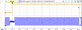
Why does this happen?
Also, I am using the internal clock for timer operation, so will this have any effect?
Please check.

  • Hi,

    Can you share your code and I will have a test from my side.

    Regards,

    Zoey

  • I have attached the code.
    As you can see in the image, the internal clock is set to "SYSOSC_4MHz" in syscfg as CLK_OUT.
    (I would like to check the internal clock, but is it better to set it to another item rather than SYSOSC?)

    #include "ti_msp_dl_config.h"
    
    unsigned long   count_timer = 0;
    
    extern volatile uint32_t interruptVectors[];
    
    int main(void)
    {
        SYSCFG_DL_init();
        DL_SYSCTL_enableSleepOnExit();
        NVIC_EnableIRQ(GPIO_SWITCHES_INT_IRQN);
        NVIC_EnableIRQ(COMPARE_0_INST_INT_IRQN);
        NVIC_EnableIRQ(TIMER_0_INST_INT_IRQN);
        count_timer = 630;
        DL_TimerG_startCounter(COMPARE_0_INST);                             // COMPARE_0_INST:スタート
        while (1) {
            __WFI();
        }
    }
    
    
    void GROUP1_IRQHandler(void)
    {
        uint32_t gpioA = DL_GPIO_getEnabledInterruptStatus
                         (GPIOA,GPIO_SWITCHES_PIN_14_PIN | GPIO_SWITCHES_PIN_18_PIN);   // GPIOの保留中の割込みを確認(PIN_11とPIN_3)
    
            if ((gpioA & GPIO_SWITCHES_PIN_18_PIN) == GPIO_SWITCHES_PIN_18_PIN)         // GPIO割込み(PIN_3検出)
              {
                if (DL_GPIO_readPins(GPIO_SWITCHES_PORT, GPIO_SWITCHES_PIN_18_PIN ))    // PIN_3の状態確認
                  {
                    ;
                  }
                else                                                                    // PIN_3:入力Lで実行
                {
                    count_timer = 630;                                                  // count_timerを630にセット
                    DL_GPIO_clearPins(GPIO_LEDS_PORT, GPIO_LEDS_USER_LED_2_PIN);        // PIN_17:出力L
                }
    
                DL_GPIO_clearInterruptStatus(GPIOA, GPIO_SWITCHES_PIN_18_PIN);          // 割込みステータスのクリア
              }
    
              if ((gpioA & GPIO_SWITCHES_PIN_14_PIN) == GPIO_SWITCHES_PIN_14_PIN)         // GPIO割込み(PIN_11検出)
               {
                 if (DL_GPIO_readPins(GPIO_SWITCHES_PORT, GPIO_SWITCHES_PIN_14_PIN ))   // PIN_11の状態確認
                    {
                     ;
                    }
                 else                                                                   // PIN_11:入力Lで実行
                    {
                     DL_TimerG_startCounter(TIMER_0_INST);                              // TIMER_0_INST:スタート
                     DL_GPIO_clearPins(GPIO_LEDS_PORT, GPIO_LEDS_USER_LED_1_PIN);       // PIN_27:出力L
                    }
                 DL_GPIO_clearInterruptStatus(GPIOA, GPIO_SWITCHES_PIN_14_PIN);         // 割込みステータスのクリア
                }
    }
    
    void COMPARE_0_INST_IRQHandler(void)
    {
        DL_GPIO_togglePins(GPIO_LEDS_PORT, GPIO_LEDS_PIN_16_PIN);
        uint16_t compVal = DL_TimerG_getCaptureCompareValue(COMPARE_0_INST,DL_TIMER_CC_0_INDEX)
                + 39;
        DL_TimerG_setCaptureCompareValue(COMPARE_0_INST,
            compVal,DL_TIMER_CC_0_INDEX
            );
    
        switch (DL_TimerG_getPendingInterrupt(COMPARE_0_INST)) {                        // タイマの動作確認
            case DL_TIMER_IIDX_ZERO:                                                    // COMPARE_0_INSTのカウントが0で実行
                if(count_timer>0)                                                       // count_timerが0より大きい場合
                {
                    count_timer = count_timer-1;
                }
    
                //DL_TimerG_stopCounter(COMPARE_0_INST);                                  // COMPARE_0_INST:ストップ


        if (count_timer == 0)                                                           // count_timerが0の場合
        {
            DL_GPIO_setPins(GPIO_LEDS_PORT, GPIO_LEDS_USER_LED_2_PIN);                  // PIN_17:出力H
    
        }else if  (count_timer > 0)                                                     // count_timerが0より大きい場合
        {
            //DL_TimerG_startCounter(COMPARE_0_INST);                                     // COMPARE_0_INST:スタート
        }
        break;
                default:
                    break;
        }
    }
    
    void TIMER_0_INST_IRQHandler(void)
    {
        switch (DL_TimerG_getPendingInterrupt(TIMER_0_INST)) {                          // タイマの動作確認
                case DL_TIMER_IIDX_ZERO:                                                // TIMER_0_INSTのカウントが0で実行
                DL_GPIO_setPins(GPIO_LEDS_PORT, GPIO_LEDS_USER_LED_1_PIN);              // PIN_11:出力H
                DL_TimerG_stopCounter(TIMER_0_INST);                                    // TIMER_0_INST:ストップ
                break;
                        default:
                            break;
                    }
    }
    

    #include "ti_msp_dl_config.h"
    
    /*
     *  ======== SYSCFG_DL_init ========
     *  Perform any initialization needed before using any board APIs
     */
    SYSCONFIG_WEAK void SYSCFG_DL_init(void)
    {
        SYSCFG_DL_initPower();
        SYSCFG_DL_GPIO_init();
        /* Module-Specific Initializations*/
        SYSCFG_DL_SYSCTL_init();
        SYSCFG_DL_COMPARE_0_init();
        SYSCFG_DL_TIMER_0_init();
    }
    
    SYSCONFIG_WEAK void SYSCFG_DL_initPower(void)
    {
        DL_GPIO_reset(GPIOA);
        DL_TimerG_reset(COMPARE_0_INST);
        DL_TimerG_reset(TIMER_0_INST);
    
        DL_GPIO_enablePower(GPIOA);
        DL_TimerG_enablePower(COMPARE_0_INST);
        DL_TimerG_enablePower(TIMER_0_INST);
        delay_cycles(POWER_STARTUP_DELAY);
    }
    
    SYSCONFIG_WEAK void SYSCFG_DL_GPIO_init(void)
    {
    
        DL_GPIO_initPeripheralOutputFunction(GPIO_CLKOUT_IOMUX, GPIO_CLKOUT_IOMUX_FUNC);
        DL_GPIO_enableOutput(GPIO_CLKOUT_PORT, GPIO_CLKOUT_PIN);
    
        DL_GPIO_initPeripheralInputFunction(GPIO_COMPARE_0_C0_IOMUX,GPIO_COMPARE_0_C0_IOMUX_FUNC);
    
        DL_GPIO_initDigitalOutput(GPIO_LEDS_USER_LED_1_IOMUX);
    
        DL_GPIO_initDigitalOutput(GPIO_LEDS_USER_LED_2_IOMUX);
    
        DL_GPIO_initDigitalOutput(GPIO_LEDS_PIN_16_IOMUX);
    
        DL_GPIO_initDigitalInputFeatures(GPIO_SWITCHES_PIN_14_IOMUX,
    		 DL_GPIO_INVERSION_DISABLE, DL_GPIO_RESISTOR_PULL_UP,
    		 DL_GPIO_HYSTERESIS_DISABLE, DL_GPIO_WAKEUP_DISABLE);
    
        DL_GPIO_initDigitalInputFeatures(GPIO_SWITCHES_PIN_18_IOMUX,
    		 DL_GPIO_INVERSION_DISABLE, DL_GPIO_RESISTOR_PULL_UP,
    		 DL_GPIO_HYSTERESIS_DISABLE, DL_GPIO_WAKEUP_DISABLE);
    
        DL_GPIO_clearPins(GPIOA, GPIO_LEDS_USER_LED_1_PIN |
    		GPIO_LEDS_USER_LED_2_PIN |
    		GPIO_LEDS_PIN_16_PIN);
        DL_GPIO_enableOutput(GPIOA, GPIO_LEDS_USER_LED_1_PIN |
    		GPIO_LEDS_USER_LED_2_PIN |
    		GPIO_LEDS_PIN_16_PIN);
        DL_GPIO_setLowerPinsPolarity(GPIOA, DL_GPIO_PIN_11_EDGE_FALL |
    		DL_GPIO_PIN_3_EDGE_FALL);
        DL_GPIO_clearInterruptStatus(GPIOA, GPIO_SWITCHES_PIN_14_PIN |
    		GPIO_SWITCHES_PIN_18_PIN);
        DL_GPIO_enableInterrupt(GPIOA, GPIO_SWITCHES_PIN_14_PIN |
    		GPIO_SWITCHES_PIN_18_PIN);
    
    }


    SYSCONFIG_WEAK void SYSCFG_DL_SYSCTL_init(void)
    {
        DL_SYSCTL_setSYSOSCFreq(DL_SYSCTL_SYSOSC_FREQ_4M);
        DL_SYSCTL_enableMFCLK();
        DL_SYSCTL_setMCLKDivider(DL_SYSCTL_MCLK_DIVIDER_DISABLE);
        DL_SYSCTL_enableExternalClock(DL_SYSCTL_CLK_OUT_SOURCE_SYSOSC,
    		DL_SYSCTL_CLK_OUT_DIVIDE_DISABLE);
    
    	//Low Power Mode is configured to be SLEEP0
        DL_SYSCTL_setBORThreshold(DL_SYSCTL_BOR_THRESHOLD_LEVEL_0);
    
    }


    /*
     * Timer clock configuration to be sourced by MFCLK /  (4000000 Hz)
     * timerClkFreq = (timerClkSrc / (timerClkDivRatio * (timerClkPrescale + 1)))
     *   4000000 Hz = 4000000 Hz / (1 * (0 + 1))
     */
    static const DL_TimerG_ClockConfig gCOMPARE_0ClockConfig = {
        .clockSel    = DL_TIMER_CLOCK_MFCLK,
        .divideRatio = DL_TIMER_CLOCK_DIVIDE_1,
        .prescale = 0U
    };
    
    static const DL_TimerG_CompareConfig gCOMPARE_0CompareConfig = {
        .compareMode    = DL_TIMER_COMPARE_MODE_EDGE_COUNT,
        .count          = 39,
        .startTimer     = DL_TIMER_STOP,
        .edgeDetectMode = DL_TIMER_COMPARE_EDGE_DETECTION_MODE_RISING,
        .inputChan      = DL_TIMER_INPUT_CHAN_0,
        .inputInvMode   = DL_TIMER_CC_INPUT_INV_NOINVERT,
    };
    
    SYSCONFIG_WEAK void SYSCFG_DL_COMPARE_0_init(void) {
    
        DL_TimerG_setClockConfig(COMPARE_0_INST,
            (DL_TimerG_ClockConfig *) &gCOMPARE_0ClockConfig);
        DL_TimerG_initCompareMode(COMPARE_0_INST,
            (DL_TimerG_CompareConfig *) &gCOMPARE_0CompareConfig);
        DL_TimerG_enableInterrupt(COMPARE_0_INST , DL_TIMERG_INTERRUPT_ZERO_EVENT);


        DL_TimerG_enableClock(COMPARE_0_INST);


    }


    /*
     * Timer clock configuration to be sourced by MFCLK /  (4000000 Hz)
     * timerClkFreq = (timerClkSrc / (timerClkDivRatio * (timerClkPrescale + 1)))
     *   4000000 Hz = 4000000 Hz / (1 * (0 + 1))
     */
    static const DL_TimerG_ClockConfig gTIMER_0ClockConfig = {
        .clockSel    = DL_TIMER_CLOCK_MFCLK,
        .divideRatio = DL_TIMER_CLOCK_DIVIDE_1,
        .prescale    = 0U,
    };
    
    /*
     * Timer load value (where the counter starts from) is calculated as (timerPeriod * timerClockFreq) - 1
     * TIMER_0_INST_LOAD_VALUE = (1.7 ms * 4000000 Hz) - 1
     */
    static const DL_TimerG_TimerConfig gTIMER_0TimerConfig = {
        .period     = TIMER_0_INST_LOAD_VALUE,
        .timerMode  = DL_TIMER_TIMER_MODE_ONE_SHOT,
        .startTimer = DL_TIMER_STOP,
    };
    
    SYSCONFIG_WEAK void SYSCFG_DL_TIMER_0_init(void) {
    
        DL_TimerG_setClockConfig(TIMER_0_INST,
            (DL_TimerG_ClockConfig *) &gTIMER_0ClockConfig);
    
        DL_TimerG_initTimerMode(TIMER_0_INST,
            (DL_TimerG_TimerConfig *) &gTIMER_0TimerConfig);
        DL_TimerG_enableInterrupt(TIMER_0_INST , DL_TIMERG_INTERRUPT_ZERO_EVENT);
        DL_TimerG_enableClock(TIMER_0_INST);


        DL_TimerG_setExternalTriggerEvent(TIMER_0_INST,
            DL_TIMER_EXT_TRIG_SEL_TRIG_SUB_0);
    
        DL_TimerG_enableExternalTrigger(TIMER_0_INST);
        DL_TimerG_setCaptureCompareInput(TIMER_0_INST,
            DL_TIMER_CC_INPUT_INV_NOINVERT, DL_TIMER_CC_IN_SEL_TRIG,
            DL_TIMER_CC_0_INDEX);
    
        DL_TimerG_setCaptureCompareCtl(TIMER_0_INST, DL_TIMER_CC_MODE_CAPTURE,
            DL_TIMER_CC_LCOND_TRIG_RISE, DL_TIMER_CC_0_INDEX);
    
        DL_TimerG_setSubscriberChanID(TIMER_0_INST,
            DL_TIMER_SUBSCRIBER_INDEX_0, TIMER_0_INST_SUB_0_CH);
    
    }

  • Hi,

    Thanks for your information, I will test step by step to find the root cause.

    By the way can you share your syscfg file, I think it is the best way to know your clock configuration quickly.

    B.R.

    Zoey

  • Attach the syscfg file.
    Thank you.

    syscfg.zip

  • Hi,

    I have tested from my side. As the MCU enter into GPIO interrupt not trigger timer-compare, everything goes well. Can you also have a try?

    And I want to make clear the orange waveform is which GPIO. 

    Regards,

    Zoey

  • 「As the MCU enter into GPIO interrupt not trigger timer-compare, everything goes well.」

    What does the above mean? I'd like to know more about it.

    The orange waveform uses USER_LED_1 = Pin 27 for output.

    In addition, Pin 16 and Pin 17 are used as outputs,
    and if any of the outputs are inverted, the frequency output will be strange.

  • Hi, 

    Zoey is OOO for next two weeks.

    I will help Zoey test this issue.

    Regards,

    Helic

  • Hi, 

    I have reproduce this issue and try to find some method to solve it~

    It may caused by GPIO interrupt with SYSOSC set to 4MHz.

    E2E_SYSOSC4MHz_CLKOutput_L1306_nortos_ticlang.zip

    Regards,

    Helic

  • Thank you for your investigation.
    I understand that this problem also occurs when a GPIO interrupt occurs.
    First of all, I would be grateful if you could find a solution that prevents this problem from occurring when the GPIO output goes from High to Low or Low to High.
    Also, is it possible that the problem does not occur if the output is inverted in the main program, but does occur if the output is inverted in a subroutine after a GPIO interrupt?
    Thank you in advance.

  • Hi, 

    I am contacting the design team to confirm this clock output problem.

    It may take some time for reply.

    Regards,

    Helic

  • Hi, 

    Can you try to run this API when system init done?
    DL_SYSCTL_disableFastCPUEventHandling()

    This will disable SYSOSC switch from 4MHz to 32MHz when a interrupt happened.(For faster response to interrupts)

    I think this will help you a lot because I have test SYSOSC=32MHz, there is no CLOCK OUT issue.

    Regards,

    Helic

  • In the current program, does this mean that the frequency switches from 4MHz to 32MHz when an interrupt occurs?
    And then it goes back to 4MHz after the interrupt?
    Could this frequency switch be the cause of the problem?

  • Hi, 

    And then it goes back to 4MHz after the interrupt?

    It should be back to 4MHz after finishing interrupt entering.

    When running interrupt hanlder, such as switch and GPIO toggle, CPU still running at 4MHz.

    Could this frequency switch be the cause of the problem?

    Yes, this may be the reason.

    Regards,

    Helic