This thread has been locked.

If you have a related question, please click the "Ask a related question" button in the top right corner. The newly created question will be automatically linked to this question.

TM4C129ENCPDT: tm4c129encpdt

Part Number: TM4C129ENCPDT
Other Parts Discussed in Thread: EK-TM4C1294XL

Tool/software: Code Composer Studio

Hi everyone,

I'm currently working on a project that involves using Quad SPI (QSPI) communication in DMA mode. I'm looking for any articles, tutorials, or documentation that specifically cover this topic.

  • Configuration and setup for DMA mode in QSPI.
  • Code examples or sample projects demonstrating QSPI with DMA.
  • Common pitfalls and troubleshooting tips for QSPI in DMA mode.

If anyone can point me to relevant resources or share their own experiences, I would greatly appreciate it.

Thanks in advance for your help!

  • Hi,

      We have a non-DMA example for QSPI. You can find the example at C:\ti\TivaWare_C_Series-2.2.0.295\examples\boards\ek-tm4c1294xl\ssi_quad_mode.

      We have a uDMA example that demonstrates transfers between two memories and also between memory and UART. We don't have an uDMA example for QSPI. However, you can adapt the example for uDMA for UART to SPI. The example can be found at  C:\ti\TivaWare_C_Series-2.2.0.295\examples\boards\ek-tm4c1294xl\udma_demo.

  • Hi Priya,

    The documents can be found at C:\ti\TivaWare_C_Series-2.1.4.178\docs. You can refer "SW-EK-TM4C1294XL-UG-2.1.4.178" for Example Applications. This may be useful to check the possibility of your requirement and implementation. Hope this helps to you.

  • Hi Charles,thankyou for the response C:\ti\TivaWare_C_Series-2.2.0.295\examples\boards\ek-tm4c1294xl\ssi_quad_mode the example here is based in rtos  i am looking for examples without rtos.I tried modifying the above example without rtos but it is not working for me.Please let me know if you have any suggestions.

    Part number: ek tm4c129exl evaluation board

    Threads: TivaWare_C_Series-2.2.0.295

    #include <stdio.h>
    #include <stdint.h>
    #include <stdlib.h>
    #include <stdbool.h>

    #include "driverlib/ssi.h"
    #include "driverlib/sysctl.h"
    #include "driverlib/pin_map.h"
    #include "driverlib/interrupt.h"
    #include "driverlib/gpio.h"

    #include "inc/hw_ints.h"
    #include "inc/hw_ssi.h"
    #include "inc/hw_memmap.h"

    #define configCPU_CLOCK_HZ ( ( unsigned long ) 120000000 )
    // Global variables for receiving data
    uint32_t g_pui32DataRx1[4];
    uint32_t g_ui32Index = 0;
    // Function prototypes
    static void prvConfigureSSIMaster(void);
    static void prvConfigureSSISlave(void);
    static void prvSSITransmitTask(void);
    static void prvSSIReceiveTask(void);
    void delayMs(int ms);
    int main(void)
    {
    // Configure and initialize SSI0 as master
    prvConfigureSSIMaster();

    // Configure and initialize SSI1 as slave
    prvConfigureSSISlave();
    prvSSITransmitTask();
    prvSSIReceiveTask();
    while (1)
    {

    }

    return 0;
    }
    static void prvConfigureSSIMaster(void)
    {
    uint32_t ui32DummyRead;

    /* The SSI0 peripheral must be enabled for use. */
    SysCtlPeripheralEnable(SYSCTL_PERIPH_SSI0);

    /* This example uses Port A[7:2] for the SSI0 pins. The GPIO port needs to
    * be enabled so those pins can be used. */
    SysCtlPeripheralEnable(SYSCTL_PERIPH_GPIOA);

    /* Configure the GPIO settings for the SSI pins. This function also gives
    * control of these pins to the SSI hardware. Consult the data sheet to
    * see which functions are allocated per pin. */

    /* Configure the pin muxing for SSI0 functions. SSI0 uses PortA for the
    * SSICLK, SSIFss and the 4 data pins. GPIO ports need to be enabled so
    * those pins can be used.
    * The GPIO pins are assigned as follows:
    * PA7 - SSI0XDAT3
    * PA6 - SSI0XDAT2
    * PA5 - SSI0XDAT1
    * PA4 - SSI0XDAT0
    * PA3 - SSI0Fss
    * PA2 - SSI0CLK */
    GPIOPinConfigure(GPIO_PA2_SSI0CLK);
    GPIOPinConfigure(GPIO_PA3_SSI0FSS);
    GPIOPinConfigure(GPIO_PA4_SSI0XDAT0);
    GPIOPinConfigure(GPIO_PA5_SSI0XDAT1);
    GPIOPinConfigure(GPIO_PA6_SSI0XDAT2);
    GPIOPinConfigure(GPIO_PA7_SSI0XDAT3);

    GPIOPinTypeSSI(GPIO_PORTA_BASE, GPIO_PIN_7 | GPIO_PIN_6 | GPIO_PIN_5 |
    GPIO_PIN_4 | GPIO_PIN_3 | GPIO_PIN_2);

    /* Configure and enable the SSI0 port for SPI master mode. Use SSI0,
    * system clock supply, idle clock level low and active low clock in legacy
    * Freescale SPI mode, master mode, 2MHz SSI frequency, and 8-bit data. For
    * SPI mode, you can set the polarity of the SSI clock when the SSI unit is
    * idle. You can also configure what clock edge you want to capture data
    * on. Please reference the device datasheet for more information on the
    * different SPI modes. */
    SSIConfigSetExpClk(SSI0_BASE, configCPU_CLOCK_HZ, SSI_FRF_MOTO_MODE_0,
    SSI_MODE_MASTER,
    2000000, 8);

    /* Enable Quad-SSI mode for SSI0. */
    SSIAdvModeSet(SSI0_BASE, SSI_ADV_MODE_QUAD_WRITE);

    /* Hold the Fss pin low during transfers. The Fss will be controlled
    * directly by the SSIAdvDataPutFrameEnd(). If calling
    * SSIAdvDataPutFrameEnd to write data to the FIFO, the Fss is de-asserted
    * for the corresponding data. */
    SSIAdvFrameHoldEnable(SSI0_BASE);

    /* Enable the SSI0 module. */
    SSIEnable(SSI0_BASE);

    /* Read any residual data from the SSI port. This makes sure the receive
    * FIFOs are empty, so we don't read any unwanted junk. This is done here
    * because the SPI SSI mode is full-duplex, which allows you to send and
    * receive at the same time. The SSIDataGetNonBlocking function returns
    * "true" when data was returned, and "false" when no data was returned.
    * The "non-blocking" function checks if there is any data in the receive
    * FIFO and does not "hang" if there isn't. */
    while (SSIDataGetNonBlocking(SSI0_BASE, &ui32DummyRead))
    {
    }
    }
    static void prvConfigureSSISlave(void)
    {
    uint32_t ui32DummyRead;

    /* The SSI1 peripheral must be enabled for use. */
    SysCtlPeripheralEnable(SYSCTL_PERIPH_SSI1);

    /* This example uses Port B, D and E for the SSI1 pins. The GPIO port
    * needs to be enabled so those pins can be used. */
    SysCtlPeripheralEnable(SYSCTL_PERIPH_GPIOB);
    SysCtlPeripheralEnable(SYSCTL_PERIPH_GPIOD);
    SysCtlPeripheralEnable(SYSCTL_PERIPH_GPIOE);

    /* Configure the GPIO settings for the SSI pins. This function also gives
    * control of these pins to the SSI hardware. Consult the data sheet to
    * see which functions are allocated per pin. */

    /* Configure the pin muxing for SSI1 functions. SSI1 uses
    * PortB, PortD and PortE for the SSICLK, SSIFss and the 4 data pins.
    * GPIO ports need to be enabled so those pins can be used.
    * The GPIO pins are assigned as follows:
    * PD5 - SSI1XDAT3
    * PD4 - SSI1XDAT2
    * PE5 - SSI1XDAT1
    * PE4 - SSI1XDAT0
    * PB4 - SSI1Fss
    * PB5 - SSI1CLK */
    GPIOPinConfigure(GPIO_PB5_SSI1CLK);
    GPIOPinConfigure(GPIO_PB4_SSI1FSS);
    GPIOPinConfigure(GPIO_PE4_SSI1XDAT0);
    GPIOPinConfigure(GPIO_PE5_SSI1XDAT1);
    GPIOPinConfigure(GPIO_PD4_SSI1XDAT2);
    GPIOPinConfigure(GPIO_PD5_SSI1XDAT3);

    GPIOPinTypeSSI(GPIO_PORTB_BASE, GPIO_PIN_5 | GPIO_PIN_4);
    GPIOPinTypeSSI(GPIO_PORTD_BASE, GPIO_PIN_5 | GPIO_PIN_4);
    GPIOPinTypeSSI(GPIO_PORTE_BASE, GPIO_PIN_5 | GPIO_PIN_4);

    /* Configure and enable the SSI1 port for SPI slave mode with matching
    * SPI mode, clock speed, and data size parameters as the master. */
    SSIConfigSetExpClk(SSI1_BASE, configCPU_CLOCK_HZ, SSI_FRF_MOTO_MODE_0,
    SSI_MODE_SLAVE,
    2000000, 8);

    /* Enable Quad-SSI mode for SSI1. */
    SSIAdvModeSet(SSI1_BASE, SSI_ADV_MODE_QUAD_READ);

    /* Enable SSI1 interrupt on RX FIFO half full or more. */
    SSIIntEnable(SSI1_BASE, SSI_RXFF);

    /* Enable the SSI1 interrupt in the NVIC. */
    IntEnable(INT_SSI1);

    /* Enable the SSI1 module. */
    SSIEnable(SSI1_BASE);

    /* Read any residual data from the SSI port. This makes sure the receive
    * FIFOs are empty, so we don't read any unwanted junk. This is done here
    * because the SPI SSI mode is full-duplex, which allows you to send and
    * receive at the same time. The SSIDataGetNonBlocking function returns
    * "true" when data was returned, and "false" when no data was returned.
    * The "non-blocking" function checks if there is any data in the receive
    * FIFO and does not "hang" if there isn't. */
    while (SSIDataGetNonBlocking(SSI1_BASE, &ui32DummyRead))
    {
    }
    }
    static void prvSSITransmitTask(void)
    {
    uint32_t pui32DataTx0[4] = {'T', 'I', 'V', 'A'};
    int i=0;
    /* Dummy write to start slave which is required for Quad-SSI mode operation. */
    SSIDataPut(SSI0_BASE, 0);
    for (i = 0; i < 4; i++) {
    /* Check if the last data byte is queued up to be sent. */
    if (i == (4 - 1)) {
    /* Calling SSIAdvDataPutFrameEnd on the last data will put out the
    * data and de-assert the Fss pin. */
    SSIAdvDataPutFrameEnd(SSI0_BASE, pui32DataTx0[i]);
    } else {
    /* Send the data using the "blocking" put function. */
    SSIDataPut(SSI0_BASE, pui32DataTx0[i]);
    }
    }
    }

    static void prvSSIReceiveTask(void)
    {
    uint32_t pui32DataRx1[4];
    uint32_t ui32Index;

    /* Check if there is data available in the receive FIFO */
    while (!SSIIntStatus(SSI1_BASE, SSI_RXFF))
    {
    delayMs(50);
    }

    /* Receive the data */
    for (ui32Index = 0; ui32Index < 4; ui32Index++)
    {
    /* Receive the data using the "blocking" Get function. */
    SSIDataGet(SSI1_BASE,&pui32DataRx1[ui32Index]);

    /* Since we are using 8-bit data, mask off the MSB. */
    pui32DataRx1[ui32Index] &= 0x00FF;
    }
    }

    // SSI1 interrupt handler
    void SSI1IntHandler(void)
    {
    uint32_t ui32Status;

    // Read the interrupt status
    ui32Status = SSIIntStatus(SSI1_BASE, true);

    // Clear the asserted interrupts
    SSIIntClear(SSI1_BASE, ui32Status);

    // Check if the interrupt is due to RX FIFO half full
    if (ui32Status & SSI_RXFF)
    {
    // Receive the data
    while (SSIDataGetNonBlocking(SSI1_BASE, &g_pui32DataRx1[g_ui32Index]) && (g_ui32Index < 4))
    {
    // Since we are using 8-bit data, mask off the MSB
    g_pui32DataRx1[g_ui32Index] &= 0x00FF;

    // Increment the index
    g_ui32Index++;
    }

    // If all data received
    if (g_ui32Index >= 4)
    {
    // Call the receive task function
    prvSSIReceiveTask();

    // Reset the index for the next reception
    g_ui32Index = 0;
    }
    }
    }
    // Delay function
    void delayMs(int ms) {
    SysCtlDelay((configCPU_CLOCK_HZ / (3 * 1000)) * ms);
    }

  •  C:\ti\TivaWare_C_Series-2.2.0.295\examples\boards\ek-tm4c1294xl\ssi_quad_mode the example here is based in rtos  i am looking for examples without rtos.

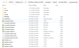
    What do you mean this is a RTOS-based example. Your understanding is incorrect. This example ssi_quad_mode is exactly a bare-metal example that does not involve RTOS. Unless you made some modification, your code listing is very different from  C:\ti\TivaWare_C_Series-2.2.0.295\examples\boards\ek-tm4c1294xl\ssi_quad_mode\ssi_quad_mode.c file. See below. 

    #include <stdbool.h>
    #include <stdint.h>
    #include "inc/hw_memmap.h"
    #include "inc/hw_ints.h"
    #include "driverlib/debug.h"
    #include "driverlib/gpio.h"
    #include "driverlib/interrupt.h"
    #include "driverlib/pin_map.h"
    #include "driverlib/rom.h"
    #include "driverlib/rom_map.h"
    #include "driverlib/ssi.h"
    #include "driverlib/sysctl.h"
    #include "driverlib/uart.h"
    #include "utils/uartstdio.h"
    
    //*****************************************************************************
    //
    //! \addtogroup example_list
    //! <h1>Quad-SSI Master (ssi_quad_mode)</h1>
    //!
    //! This example shows how to configure SSI0 as a Quad-SSI Master and SSI1 as a
    //! Quad-SSI slave.  The master device will send four characters to the slave
    //! device using the advanced Quad mode.  In Quad-SSI mode, four bits are sent
    //! on each SSI Clock pulse.  Once the Quad-SSI slave receives the four
    //! characters in its receive FIFO it will generate an interrupt.
    //!
    //! This example uses the following peripherals and I/O signals.  You must
    //! review these and change as needed for your own board:
    //! - SSI0 peripheral
    //! - GPIO Port A peripheral (for SSI0 pins)
    //! - SSI0Clk    - PA2
    //! - SSI0Fss    - PA3
    //! - SSI0XDAT0  - PA4
    //! - SSI0XDAT1  - PA5
    //! - SSI0XDAT2  - PA6
    //! - SSI0XDAT3  - PA7
    //!
    //! - SSI1 peripheral
    //! - GPIO Port B, D, E peripheral (for SSI1 pins)
    //! - SSI1Clk    - PB5
    //! - SSI1Fss    - PB4
    //! - SSI1XDAT0  - PE4
    //! - SSI1XDAT1  - PE5
    //! - SSI1XDAT2  - PD4
    //! - SSI1XDAT3  - PD5
    //!
    //! This example requires board level connection between SSI0 and SSI1.
    //!
    //! UART0, connected to the Virtual Serial Port and running at 115,200, 8-N-1,
    //! is used to display messages from this application.
    //
    //*****************************************************************************
    
    //****************************************************************************
    //
    // The variable g_ui32SysClock contains the system clock frequency in Hz.
    //
    //****************************************************************************
    uint32_t g_ui32SysClock;
    
    //*****************************************************************************
    //
    // Global flag to indicate data was received
    //
    //*****************************************************************************
    volatile uint32_t g_bReceiveFlag = 0;
    
    //*****************************************************************************
    //
    // Number of bytes to send and receive.
    //
    //*****************************************************************************
    #define NUM_SSI_DATA            4
    
    //*****************************************************************************
    //
    // The error routine that is called if the driver library encounters an error.
    //
    //*****************************************************************************
    #ifdef DEBUG
    void
    __error__(char *pcFilename, uint32_t ui32Line)
    {
    }
    #endif
    
    //*****************************************************************************
    //
    // Configure the UART and its pins. This must be called before UARTprintf().
    //
    //*****************************************************************************
    void
    ConfigureUART(void)
    {
        //
        // Enable the GPIO Peripheral used by the UART.
        //
        ROM_SysCtlPeripheralEnable(SYSCTL_PERIPH_GPIOA);
    
        //
        // Enable UART0.
        //
        ROM_SysCtlPeripheralEnable(SYSCTL_PERIPH_UART0);
    
        //
        // Configure GPIO Pins for UART mode.
        //
        ROM_GPIOPinConfigure(GPIO_PA0_U0RX);
        ROM_GPIOPinConfigure(GPIO_PA1_U0TX);
        ROM_GPIOPinTypeUART(GPIO_PORTA_BASE, GPIO_PIN_0 | GPIO_PIN_1);
    
        //
        // Initialize the UART for console I/O.
        //
        UARTStdioConfig(0, 115200, g_ui32SysClock);
    }
    
    //*****************************************************************************
    //
    // When the received FIFO is half-full, an interrupt will be generated.
    //
    //*****************************************************************************
    void
    SSI1IntHandler(void)
    {
        uint32_t ui32Status;
    
        //
        // Read the SSI Masked Interrupt Status.
        //
        ui32Status = MAP_SSIIntStatus(SSI1_BASE, true);
    
        //
        // Clear the SSI interrupt.
        //
        MAP_SSIIntClear(SSI1_BASE, ui32Status);
    
        //
        // Turn off the RX FIFO interrupt.
        //
        MAP_SSIIntDisable(SSI1_BASE, SSI_RXFF);
    
        //
        // Toggle flag to indicate that data has been received.
        //
        g_bReceiveFlag = 1;
    }
    
    
    //*****************************************************************************
    //
    // Configure SSI0 in Quad-SSI master Freescale (SPI) mode and SSI1 in Quad-SSI
    // slave mode.  The SSI0 will send out 4 bytes of data in advanced Quad mode
    // and the SSI1 slave will receive the 4 bytes of data also in Quad mode. The
    // slave will generate interrupt upon receiving the 4 bytes of data.
    //
    //*****************************************************************************
    int
    main(void)
    {
        uint32_t pui32DataTx[NUM_SSI_DATA];
        uint32_t pui32DataRx[NUM_SSI_DATA];
        uint32_t ui32Index;
    
        //
        // Run from the PLL at 120 MHz.
        // Note: SYSCTL_CFG_VCO_240 is a new setting provided in TivaWare 2.2.x and
        // later to better reflect the actual VCO speed due to SYSCTL#22.
        //
        g_ui32SysClock = MAP_SysCtlClockFreqSet((SYSCTL_XTAL_25MHZ |
                                                 SYSCTL_OSC_MAIN |
                                                 SYSCTL_USE_PLL |
                                                 SYSCTL_CFG_VCO_240), 120000000);
    
        //
        // Set up the serial console to use for displaying messages.
        //
        ConfigureUART();
    
        //
        // Display the setup on the console.
        //
        UARTprintf("SSI ->\n");
        UARTprintf("Mode: Advanced Quad-SPI\n");
        UARTprintf("Data: 8-bit\n\n");
    
        //
        // The SSI0 and SSI1 peripheral must be enabled for use.
        //
        MAP_SysCtlPeripheralEnable(SYSCTL_PERIPH_SSI0);
        MAP_SysCtlPeripheralEnable(SYSCTL_PERIPH_SSI1);
    
        //
        // For this example SSI0 is used with PortA[7:2].  The SSI1 uses
        // PortB, PortD and PortE for the SSICLK, SSIFss and the 4 data pins.
        // GPIO ports need to be enabled so those pins can be used.
        //
        MAP_SysCtlPeripheralEnable(SYSCTL_PERIPH_GPIOA);
        MAP_SysCtlPeripheralEnable(SYSCTL_PERIPH_GPIOB);
        MAP_SysCtlPeripheralEnable(SYSCTL_PERIPH_GPIOD);
        MAP_SysCtlPeripheralEnable(SYSCTL_PERIPH_GPIOE);
    
        //
        // Configure the pin muxing for SSI0 functions on PA[7:2].
        // Configure the pin muxing for SSI1 functions on PB, PD and PE.
        //
        MAP_GPIOPinConfigure(GPIO_PA2_SSI0CLK);
        MAP_GPIOPinConfigure(GPIO_PA3_SSI0FSS);
        MAP_GPIOPinConfigure(GPIO_PA4_SSI0XDAT0);
        MAP_GPIOPinConfigure(GPIO_PA5_SSI0XDAT1);
        MAP_GPIOPinConfigure(GPIO_PA6_SSI0XDAT2);
        MAP_GPIOPinConfigure(GPIO_PA7_SSI0XDAT3);
    
        MAP_GPIOPinConfigure(GPIO_PB5_SSI1CLK);
        MAP_GPIOPinConfigure(GPIO_PB4_SSI1FSS);
        MAP_GPIOPinConfigure(GPIO_PE4_SSI1XDAT0);
        MAP_GPIOPinConfigure(GPIO_PE5_SSI1XDAT1);
        MAP_GPIOPinConfigure(GPIO_PD4_SSI1XDAT2);
        MAP_GPIOPinConfigure(GPIO_PD5_SSI1XDAT3);
    
        //
        // Configure the GPIO settings for the SSI pins.  This function also gives
        // control of these pins to the SSI hardware.  Consult the data sheet to
        // see which functions are allocated per pin.
        // The pins are assigned as follows:
        //      SSI0
        //      PA7 - SSI0XDAT3
        //      PA6 - SSI0XDAT2
        //      PA5 - SSI0XDAT1
        //      PA4 - SSI0XDAT0
        //      PA3 - SSI0Fss
        //      PA2 - SSI0CLK
        //      SSI1
        //      PD5 - SSI1XDAT3
        //      PD4 - SSI1XDAT2
        //      PE5 - SSI1XDAT1
        //      PE4 - SSI1XDAT0
        //      PB4 - SSI1Fss
        //      PB5 - SSI1CLK
        //
        MAP_GPIOPinTypeSSI(GPIO_PORTA_BASE, GPIO_PIN_7 | GPIO_PIN_6 | GPIO_PIN_5 |
                           GPIO_PIN_4 | GPIO_PIN_3 | GPIO_PIN_2);
        MAP_GPIOPinTypeSSI(GPIO_PORTB_BASE, GPIO_PIN_5 | GPIO_PIN_4 );
        MAP_GPIOPinTypeSSI(GPIO_PORTD_BASE, GPIO_PIN_5 | GPIO_PIN_4 );
        MAP_GPIOPinTypeSSI(GPIO_PORTE_BASE, GPIO_PIN_5 | GPIO_PIN_4 );
    
        //
        // Configure and enable the SSI0 port for SPI master mode.  Use SSI0,
        // system clock supply, idle clock level low and active low clock in
        // freescale SPI mode, master mode, 2MHz SSI frequency, and 8-bit data.
        // For SPI mode, you can set the polarity of the SSI clock when the SSI
        // unit is idle.  You can also configure what clock edge you want to
        // capture data on.  Please reference the device datasheet for more
        // information on the different SPI modes.
        //
        MAP_SSIConfigSetExpClk(SSI0_BASE, g_ui32SysClock, SSI_FRF_MOTO_MODE_0,
                               SSI_MODE_MASTER, 2000000, 8);
    
        //
        // Configure and enable the SSI1 port for SPI slave mode.
        //
        MAP_SSIConfigSetExpClk(SSI1_BASE, g_ui32SysClock, SSI_FRF_MOTO_MODE_0,
                               SSI_MODE_SLAVE, 2000000, 8);
    
        //
        // Enable Quad-SSI mode for both SSI0 and SSI1.
        //
        MAP_SSIAdvModeSet(SSI0_BASE, SSI_ADV_MODE_QUAD_WRITE);
        MAP_SSIAdvModeSet(SSI1_BASE, SSI_ADV_MODE_QUAD_READ);
    
        //
        // Hold the Fss pin low during transfers.  The Fss will be controlled
        // directly by the SSIAdvDataPutFrameEnd().  If calling
        // SSIAdvDataPutFrameEnd to write data to the FIFO, the Fss is de-asserted
        // for the corresponding data.
        //
        MAP_SSIAdvFrameHoldEnable(SSI0_BASE);
    
        //
        // Enable processor interrupts.
        //
        MAP_IntMasterEnable();
    
        //
        // Enable SSI1 interrupt on RX FIFO full.
        //
        MAP_SSIIntEnable(SSI1_BASE, SSI_RXFF);
    
        //
        // Enable the SSI1 interrupts on the processor (NVIC).
        //
        MAP_IntEnable(INT_SSI1);
    
        //
        // Enable the SSI0 and SSI1 modules.
        //
        MAP_SSIEnable(SSI0_BASE);
        MAP_SSIEnable(SSI1_BASE);
    
        //
        // Read any residual data from the SSI port.  This makes sure the receive
        // FIFOs are empty, so we don't read any unwanted junk.  This is done here
        // because the SPI SSI mode is full-duplex, which allows you to send and
        // receive at the same time.  The SSIDataGetNonBlocking function returns
        // "true" when data was returned, and "false" when no data was returned.
        // The "non-blocking" function checks if there is any data in the receive
        // FIFO and does not "hang" if there isn't.
        //
        while(MAP_SSIDataGetNonBlocking(SSI0_BASE, &pui32DataRx[0]))
        {
        }
        while(MAP_SSIDataGetNonBlocking(SSI1_BASE, &pui32DataRx[0]))
        {
        }
    
        //
        // Initialize the data to send.
        //
        pui32DataTx[0] = 'Q';
        pui32DataTx[1] = 'S';
        pui32DataTx[2] = 'S';
        pui32DataTx[3] = 'I';
    
        //
        // Display indication that the SSI0 is transmitting data.
        //
        UARTprintf("SSI0 Sent:\n  ");
        UARTprintf("'Q' 'S' 'S' 'I' ");
    
        //
        // Send 4 bytes of data.
        //
        for(ui32Index = 0; ui32Index < NUM_SSI_DATA; ui32Index++)
        {
    
            //
            // Dummy write to start slave which is required for Quad-SSI
            // mode operation.
            //
            MAP_SSIDataPut(SSI1_BASE, 0);
    
            //
            // Check if the last data byte is queued up to be sent.
            //
            if (ui32Index == (NUM_SSI_DATA - 1))
            {
                //
                // Calling SSIAdvDataPutFrameEnd on the last data will put out the
                // data and de-assert the the Fss pin.
                //
                MAP_SSIAdvDataPutFrameEnd(SSI0_BASE, pui32DataTx[ui32Index]);
            }
            else
            {
                //
                // Send the data using the "blocking" put function.  This function
                // will wait until there is room in the send FIFO before returning.
                // This allows you to assure that all the data you send makes it
                // into the send FIFO.
                //
                MAP_SSIDataPut(SSI0_BASE, pui32DataTx[ui32Index]);
            }
        }
    
    
        //
        // Wait until SSI1 receives the half-full interrupt on the RX FIFO.
        //
        while (g_bReceiveFlag == 0);
    
        //
        // Display indication that the SSI is receiving data.
        //
        UARTprintf("\nSSI1 Received:\n  ");
    
        //
        // Receive 4 bytes of data.
        //
        for(ui32Index = 0; ui32Index < NUM_SSI_DATA; ui32Index++)
        {
            //
            // Receive the data using the "blocking" Get function.  This function
            // will wait until there is data in the receive FIFO before returning.
            //
            MAP_SSIDataGet(SSI1_BASE, &pui32DataRx[ui32Index]);
    
            //
            // Since we are using 8-bit data, mask off the MSB.
            //
            pui32DataRx[ui32Index] &= 0x00FF;
    
            //
            // Display the data that SSI1 received.
            //
            UARTprintf("'%c' ", pui32DataRx[ui32Index]);
        }
    
        //
        // Return no errors.
        //
        while (1);
    }

  • I think the example i have is different maybe that is why.Could you please share a link to that so i can download it.

    /*
     * ssi_quad_mode
     *
     * Copyright (C) 2022 Texas Instruments Incorporated
     * 
     * 
     *  Redistribution and use in source and binary forms, with or without 
     *  modification, are permitted provided that the following conditions 
     *  are met:
     *
     *    Redistributions of source code must retain the above copyright 
     *    notice, this list of conditions and the following disclaimer.
     *
     *    Redistributions in binary form must reproduce the above copyright
     *    notice, this list of conditions and the following disclaimer in the 
     *    documentation and/or other materials provided with the   
     *    distribution.
     *
     *    Neither the name of Texas Instruments Incorporated nor the names of
     *    its contributors may be used to endorse or promote products derived
     *    from this software without specific prior written permission.
     *
     *  THIS SOFTWARE IS PROVIDED BY THE COPYRIGHT HOLDERS AND CONTRIBUTORS 
     *  "AS IS" AND ANY EXPRESS OR IMPLIED WARRANTIES, INCLUDING, BUT NOT 
     *  LIMITED TO, THE IMPLIED WARRANTIES OF MERCHANTABILITY AND FITNESS FOR
     *  A PARTICULAR PURPOSE ARE DISCLAIMED. IN NO EVENT SHALL THE COPYRIGHT 
     *  OWNER OR CONTRIBUTORS BE LIABLE FOR ANY DIRECT, INDIRECT, INCIDENTAL, 
     *  SPECIAL, EXEMPLARY, OR CONSEQUENTIAL DAMAGES (INCLUDING, BUT NOT 
     *  LIMITED TO, PROCUREMENT OF SUBSTITUTE GOODS OR SERVICES; LOSS OF USE,
     *  DATA, OR PROFITS; OR BUSINESS INTERRUPTION) HOWEVER CAUSED AND ON ANY
     *  THEORY OF LIABILITY, WHETHER IN CONTRACT, STRICT LIABILITY, OR TORT 
     *  (INCLUDING NEGLIGENCE OR OTHERWISE) ARISING IN ANY WAY OUT OF THE USE 
     *  OF THIS SOFTWARE, EVEN IF ADVISED OF THE POSSIBILITY OF SUCH DAMAGE.
     *
    */
    
    /******************************************************************************
     *
     * This example shows how to configure SSI0 as a Quad-SSI Master and SSI1 as a
     * Quad-SSI slave.  The master device will send four characters to the slave
     * device using the advanced Quad mode.  In Quad-SSI mode, four bits are sent
     * on each SSI Clock pulse.  Once the Quad-SSI slave receives the four
     * characters in its receive FIFO it will generate an interrupt.
     *
     * This example uses the following peripherals and I/O signals.  You must
     * review these and change as needed for your own board:
     * - SSI0 peripheral
     * - GPIO Port A peripheral (for SSI0 pins)
     * - SSI0Clk    - PA2
     * - SSI0Fss    - PA3
     * - SSI0XDAT0  - PA4
     * - SSI0XDAT1  - PA5
     * - SSI0XDAT2  - PA6
     * - SSI0XDAT3  - PA7
     *
     * - SSI1 peripheral
     * - GPIO Port B, D, E peripheral (for SSI1 pins)
     * - SSI1Clk    - PB5
     * - SSI1Fss    - PB4
     * - SSI1XDAT0  - PE4
     * - SSI1XDAT1  - PE5
     * - SSI1XDAT2  - PD4
     * - SSI1XDAT3  - PD5
     *
     * This example requires board level connection between SSI0 and SSI1.
     *
     * This example uses UARTprintf for output of UART messages.  UARTprintf is not
     * a thread-safe API and is only being used for simplicity of the demonstration
     * and in a controlled manner.
     *
     * Open a terminal with 115,200 8-N-1 to see the output for this demo.
     *
     */
    
    /* Standard includes. */
    #include <stdio.h>
    #include <stdbool.h>
    #include <stdint.h>
    
    /* Kernel includes. */
    #include "FreeRTOS.h"
    #include "task.h"
    
    /* Hardware includes. */
    #include "inc/hw_memmap.h"
    #include "inc/hw_sysctl.h"
    #include "driverlib/gpio.h"
    #include "driverlib/interrupt.h"
    #include "driverlib/pin_map.h"
    #include "driverlib/rom.h"
    #include "driverlib/rom_map.h"
    #include "driverlib/sysctl.h"
    #include "driverlib/uart.h"
    #include "drivers/rtos_hw_drivers.h"
    #include "utils/uartstdio.h"
    /*-----------------------------------------------------------*/
    
    /* The system clock frequency. */
    uint32_t g_ui32SysClock;
    
    /* Set up the clock and pin configurations to run this example. */
    static void prvSetupHardware( void );
    
    /* This function sets up UART0 to be used for a console to display information
     * as the example is running. */
    static void prvConfigureUART(void);
    
    /* API to trigger the SSI task. */
    extern void vSSITaskCreate( void );
    /*-----------------------------------------------------------*/
    
    int main( void )
    {
        /* Prepare the hardware to run this example. */
    	prvSetupHardware();
    
        /* Configure the SSI peripherals for quad mode as a master / slave. */
    	vSSITaskCreate();
    
        /* Start the tasks running. */
        vTaskStartScheduler();
    
        /* If all is well, the scheduler will now be running, and the following
        line will never be reached.  If the following line does execute, then
        there was insufficient FreeRTOS heap memory available for the idle and/or
        timer tasks to be created.  See the memory management section on the
        FreeRTOS web site for more details. */
        for( ;; );
    }
    /*-----------------------------------------------------------*/
    
    static void prvSetupHardware( void )
    {
        /* Run from the PLL at configCPU_CLOCK_HZ MHz. */
        g_ui32SysClock = MAP_SysCtlClockFreqSet((SYSCTL_XTAL_25MHZ |
                SYSCTL_OSC_MAIN | SYSCTL_USE_PLL |
                SYSCTL_CFG_VCO_240), configCPU_CLOCK_HZ);
    
        /* Configure device pins. */
        PinoutSet(false, false);
    
        /* Configure UART0 to send messages to terminal. */
        prvConfigureUART();
    }
    /*-----------------------------------------------------------*/
    
    static void prvConfigureUART(void)
    {
        /* Enable GPIO port A which is used for UART0 pins.
         * TODO: change this to whichever GPIO port you are using. */
        SysCtlPeripheralEnable(SYSCTL_PERIPH_GPIOA);
    
        /* Configure the pin muxing for UART0 functions on port A0 and A1.
         * This step is not necessary if your part does not support pin muxing.
         * TODO: change this to select the port/pin you are using. */
        GPIOPinConfigure(GPIO_PA0_U0RX);
        GPIOPinConfigure(GPIO_PA1_U0TX);
    
        /* Enable UART0 so that we can configure the clock. */
        SysCtlPeripheralEnable(SYSCTL_PERIPH_UART0);
    
        /* Use the internal 16MHz oscillator as the UART clock source. */
        UARTClockSourceSet(UART0_BASE, UART_CLOCK_PIOSC);
    
        /* Select the alternate (UART) function for these pins.
         * TODO: change this to select the port/pin you are using. */
        GPIOPinTypeUART(GPIO_PORTA_BASE, GPIO_PIN_0 | GPIO_PIN_1);
    
        /* Initialize the UART for console I/O. */
        UARTStdioConfig(0, 115200, 16000000);
    }
    /*-----------------------------------------------------------*/
    
    void vApplicationMallocFailedHook( void )
    {
        /* vApplicationMallocFailedHook() will only be called if
        configUSE_MALLOC_FAILED_HOOK is set to 1 in FreeRTOSConfig.h.  It is a hook
        function that will get called if a call to pvPortMalloc() fails.
        pvPortMalloc() is called internally by the kernel whenever a task, queue,
        timer or semaphore is created.  It is also called by various parts of the
        demo application.  If heap_1.c or heap_2.c are used, then the size of the
        heap available to pvPortMalloc() is defined by configTOTAL_HEAP_SIZE in
        FreeRTOSConfig.h, and the xPortGetFreeHeapSize() API function can be used
        to query the size of free heap space that remains (although it does not
        provide information on how the remaining heap might be fragmented). */
        IntMasterDisable();
        for( ;; );
    }
    /*-----------------------------------------------------------*/
    
    void vApplicationIdleHook( void )
    {
        /* vApplicationIdleHook() will only be called if configUSE_IDLE_HOOK is set
        to 1 in FreeRTOSConfig.h.  It will be called on each iteration of the idle
        task.  It is essential that code added to this hook function never attempts
        to block in any way (for example, call xQueueReceive() with a block time
        specified, or call vTaskDelay()).  If the application makes use of the
        vTaskDelete() API function (as this demo application does) then it is also
        important that vApplicationIdleHook() is permitted to return to its calling
        function, because it is the responsibility of the idle task to clean up
        memory allocated by the kernel to any task that has since been deleted. */
    }
    /*-----------------------------------------------------------*/
    
    void vApplicationStackOverflowHook( TaskHandle_t pxTask, char *pcTaskName )
    {
        ( void ) pcTaskName;
        ( void ) pxTask;
    
        /* Run time stack overflow checking is performed if
        configCHECK_FOR_STACK_OVERFLOW is defined to 1 or 2.  This hook
        function is called if a stack overflow is detected. */
        IntMasterDisable();
        for( ;; );
    }
    /*-----------------------------------------------------------*/
    
    void *malloc( size_t xSize )
    {
        /* There should not be a heap defined, so trap any attempts to call
        malloc. */
        IntMasterDisable();
        for( ;; );
    }
    /*-----------------------------------------------------------*/


    C:\ti\TivaWare_C_Series-2.2.0.295\examples\EK-TM4C1294XL Examples\Examples\ssi_quad_mode\main.c

    "C:\ti\TivaWare_C_Series-2.2.0.295\examples\EK-TM4C1294XL Examples\Examples\ssi_quad_mode\ssi_task.c"

    /*
     * ssi_task
     *
     * Copyright (C) 2022 Texas Instruments Incorporated
     * 
     * 
     *  Redistribution and use in source and binary forms, with or without 
     *  modification, are permitted provided that the following conditions 
     *  are met:
     *
     *    Redistributions of source code must retain the above copyright 
     *    notice, this list of conditions and the following disclaimer.
     *
     *    Redistributions in binary form must reproduce the above copyright
     *    notice, this list of conditions and the following disclaimer in the 
     *    documentation and/or other materials provided with the   
     *    distribution.
     *
     *    Neither the name of Texas Instruments Incorporated nor the names of
     *    its contributors may be used to endorse or promote products derived
     *    from this software without specific prior written permission.
     *
     *  THIS SOFTWARE IS PROVIDED BY THE COPYRIGHT HOLDERS AND CONTRIBUTORS 
     *  "AS IS" AND ANY EXPRESS OR IMPLIED WARRANTIES, INCLUDING, BUT NOT 
     *  LIMITED TO, THE IMPLIED WARRANTIES OF MERCHANTABILITY AND FITNESS FOR
     *  A PARTICULAR PURPOSE ARE DISCLAIMED. IN NO EVENT SHALL THE COPYRIGHT 
     *  OWNER OR CONTRIBUTORS BE LIABLE FOR ANY DIRECT, INDIRECT, INCIDENTAL, 
     *  SPECIAL, EXEMPLARY, OR CONSEQUENTIAL DAMAGES (INCLUDING, BUT NOT 
     *  LIMITED TO, PROCUREMENT OF SUBSTITUTE GOODS OR SERVICES; LOSS OF USE,
     *  DATA, OR PROFITS; OR BUSINESS INTERRUPTION) HOWEVER CAUSED AND ON ANY
     *  THEORY OF LIABILITY, WHETHER IN CONTRACT, STRICT LIABILITY, OR TORT 
     *  (INCLUDING NEGLIGENCE OR OTHERWISE) ARISING IN ANY WAY OUT OF THE USE 
     *  OF THIS SOFTWARE, EVEN IF ADVISED OF THE POSSIBILITY OF SUCH DAMAGE.
     *
    */
    
    /******************************************************************************
     *
     * vSSITaskCreate is called by main() to configure SSI0 as a master and SSI1
     * as a slave. vSSITaskCreate also creates two tasks: prvSSITransmitTask and
     * prvSSIReceiveTask. The transmit task sends four bytes to SSI0 and deletes
     * the task itself after four bytes are transmitted. The receive task waits for
     * the notification released from the xSSI1Handler ISR indicating the SSI1
     * receive FIFO is half full or more. Once the receive task is unblocked, it
     * reads and processes the data by means of displaying the received bytes to
     * the terminal window.
     *
     */
    
    /* Standard includes. */
    #include <stdio.h>
    #include <stdint.h>
    #include <stdlib.h>
    #include <stdbool.h>
    
    /* Kernel includes. */
    #include "FreeRTOS.h"
    #include "task.h"
    #include "semphr.h"
    
    /* Hardware includes. */
    #include "inc/hw_ints.h"
    #include "inc/hw_memmap.h"
    #include "driverlib/gpio.h"
    #include "driverlib/interrupt.h"
    #include "driverlib/pin_map.h"
    #include "driverlib/ssi.h"
    #include "driverlib/sysctl.h"
    #include "drivers/rtos_hw_drivers.h"
    #include "utils/uartstdio.h"
    /*-----------------------------------------------------------*/
    
    /*
     * Number of bytes to send and receive.
     */
    #define NUM_SSI_DATA            4
    
    /*
     * Declare a variable that is used to hold the handle of the SSI1
     * interrupt task.
     */
    TaskHandle_t xSSI1IntTask = NULL;
    
    /*
     * The tasks as described in the comments at the top of this file.
     */
    static void prvSSITransmitTask( void *pvParameters );
    static void prvSSIReceiveTask( void *pvParameters );
    
    /*
     * Called by main() to create the SSI tasks.
     */
    void vSSITaskCreate( void );
    
    /*
     * Configure the SSI peripheral for both Master and Slave operation.
     */
    static void prvConfigureSSIMaster( void );
    static void prvConfigureSSISlave( void );
    /*-----------------------------------------------------------*/
    
    void vSSITaskCreate( void )
    {
        /* Configure the SSI0 peripheral for Master Mode at 2MHz. */
        prvConfigureSSIMaster();
    
        /* Configure the SSI1 peripheral for Slave Mode at 2MHz. */
        prvConfigureSSISlave();
    
        /* Create the task as described in the comments at the top of this file.
         *
         * The xTaskCreate parameters in order are:
         *  - The function that implements the task.
         *  - The text name Hello task - for debug only as it is
         *    not used by the kernel.
         *  - The size of the stack to allocate to the task.
         *  - No parameter passed to the task
         *  - The priority assigned to the task.
         *  - The task handle is NULL */
        xTaskCreate( prvSSITransmitTask,
                     "SSITX",
                     configMINIMAL_STACK_SIZE,
                     NULL,
                     tskIDLE_PRIORITY + 2,
                     NULL );
    
        /* Create the task as described in the comments at the top of this file.
         *
         * The xTaskCreate parameters in order are:
         *  - The function that implements the task.
         *  - The text name Hello task - for debug only as it is
         *    not used by the kernel.
         *  - The size of the stack to allocate to the task.
         *  - No parameter passed to the task
         *  - The priority assigned to the task.
         *  - The task handle is NULL */
        xTaskCreate( prvSSIReceiveTask,
                     "SSIRX",
                     configMINIMAL_STACK_SIZE,
                     NULL,
                     tskIDLE_PRIORITY + 1,
                     &xSSI1IntTask );
    }
    /*-----------------------------------------------------------*/
    
    static void prvSSITransmitTask( void *pvParameters )
    {
    uint32_t pui32DataTx0[4] = {'T', 'I', 'V', 'A'};
    uint32_t ui32Index;
    
        ui32Index = 0;
    
        UARTprintf("SSI0 Sending:\n  ");
        UARTprintf("'T' 'I' 'V' 'A' \n");
    
        for( ;; )
        {
    
            /* Dummy write to start slave which is required for Quad-SSI
             * mode operation. */
            SSIDataPut(SSI1_BASE, 0);
    
            /* Check if the last data byte is queued up to be sent. */
            if (ui32Index == (NUM_SSI_DATA - 1))
            {
                /* Calling SSIAdvDataPutFrameEnd on the last data will put out the
                 * data and de-assert the the Fss pin. */
                SSIAdvDataPutFrameEnd(SSI0_BASE, pui32DataTx0[ui32Index]);
            }
            else
            {
                /* Send the data using the "blocking" put function.  This function
                 * will wait until there is room in the send FIFO before returning.
                 * This allows you to assure that all the data you send makes it into
                 * the send FIFO. */
                SSIDataPut(SSI0_BASE, pui32DataTx0[ui32Index]);
            }
    
            /* Increment the index. */
            ui32Index++;
    
            if (ui32Index == 4)
            {
                /* Delete the task now that data has been sent. */
                vTaskDelete(NULL);
            }
        }
    }
    /*-----------------------------------------------------------*/
    
    static void prvSSIReceiveTask( void *pvParameters )
    {
    unsigned long ulEventsToProcess;
    uint32_t pui32DataRx1[4];
    uint32_t ui32Index;
    
        for( ;; )
        {
            /* Wait to receive a notification sent directly to this task from the
             * interrupt service routine. */
            ulEventsToProcess = ulTaskNotifyTake( pdTRUE, portMAX_DELAY );
    
            if (ulEventsToProcess != 0)
            {
                /* There should be four bytes received. */
                for(ui32Index = 0; ui32Index < 4; ui32Index++)
                {
                    /* Receive the data using the "blocking" Get function.  This
                     * function will wait until there is data in the receive FIFO
                     * before returning. */
                    SSIDataGet(SSI1_BASE, &pui32DataRx1[ui32Index]);
    
                    /* Since we are using 8-bit data, mask off the MSB. */
                    pui32DataRx1[ui32Index] &= 0x00FF;
                }
    
                /* Display the data that SSI1 received. */
                UARTprintf("\nSSI1 Received:\n  ");
                UARTprintf("'%c' '%c' '%c' '%c'", pui32DataRx1[0],
                           pui32DataRx1[1], pui32DataRx1[2], pui32DataRx1[3]);
    
                /* Delete the task now that data has been printed. */
                vTaskDelete(NULL);
            }
        }
    }
    /*-----------------------------------------------------------*/
    
    static void prvConfigureSSIMaster( void )
    {
    uint32_t ui32DummyRead;
    
        /* The SSI0 peripheral must be enabled for use. */
        SysCtlPeripheralEnable(SYSCTL_PERIPH_SSI0);
    
        /* This example uses Port A[7:2] for the SSI0 pins.  The GPIO port needs to
         * be enabled so those pins can be used. */
        SysCtlPeripheralEnable(SYSCTL_PERIPH_GPIOA);
    
        /* Configure the GPIO settings for the SSI pins.  This function also gives
        * control of these pins to the SSI hardware.  Consult the data sheet to
        * see which functions are allocated per pin. */
    
        /* Configure the pin muxing for SSI0 functions.  SSI0 uses PortA for the
         * SSICLK, SSIFss and the 4 data pins. GPIO ports need to be enabled so
         * those pins can be used.
         * The GPIO pins are assigned as follows:
         *   PA7 - SSI0XDAT3
         *   PA6 - SSI0XDAT2
         *   PA5 - SSI0XDAT1
         *   PA4 - SSI0XDAT0
         *   PA3 - SSI0Fss
         *   PA2 - SSI0CLK */
         GPIOPinConfigure(GPIO_PA2_SSI0CLK);
         GPIOPinConfigure(GPIO_PA3_SSI0FSS);
         GPIOPinConfigure(GPIO_PA4_SSI0XDAT0);
         GPIOPinConfigure(GPIO_PA5_SSI0XDAT1);
         GPIOPinConfigure(GPIO_PA6_SSI0XDAT2);
         GPIOPinConfigure(GPIO_PA7_SSI0XDAT3);
    
         GPIOPinTypeSSI(GPIO_PORTA_BASE, GPIO_PIN_7 | GPIO_PIN_6 | GPIO_PIN_5 |
                            GPIO_PIN_4 | GPIO_PIN_3 | GPIO_PIN_2);
    
        /* Configure and enable the SSI0 port for SPI master mode.  Use SSI0,
         * system clock supply, idle clock level low and active low clock in legacy
         * Freescale SPI mode, master mode, 2MHz SSI frequency, and 8-bit data. For
         * SPI mode, you can set the polarity of the SSI clock when the SSI unit is
         * idle.  You can also configure what clock edge you want to capture data
         * on.  Please reference the device datasheet for more information on the
         * different SPI modes. */
        SSIConfigSetExpClk(SSI0_BASE, configCPU_CLOCK_HZ, SSI_FRF_MOTO_MODE_0,
                           SSI_MODE_MASTER, 2000000, 8);
    
        /* Enable Quad-SSI mode for SSI0. */
        SSIAdvModeSet(SSI0_BASE, SSI_ADV_MODE_QUAD_WRITE);
    
        /* Hold the Fss pin low during transfers.  The Fss will be controlled
         * directly by the SSIAdvDataPutFrameEnd().  If calling
         * SSIAdvDataPutFrameEnd to write data to the FIFO, the Fss is de-asserted
         * for the corresponding data. */
        SSIAdvFrameHoldEnable(SSI0_BASE);
    
        /* Enable the SSI0 module. */
        SSIEnable(SSI0_BASE);
    
        /* Read any residual data from the SSI port.  This makes sure the receive
         * FIFOs are empty, so we don't read any unwanted junk.  This is done here
         * because the SPI SSI mode is full-duplex, which allows you to send and
         * receive at the same time.  The SSIDataGetNonBlocking function returns
         * "true" when data was returned, and "false" when no data was returned.
         * The "non-blocking" function checks if there is any data in the receive
         * FIFO and does not "hang" if there isn't. */
        while(SSIDataGetNonBlocking(SSI0_BASE, &ui32DummyRead))
        {
        }
    }
    /*-----------------------------------------------------------*/
    
    static void prvConfigureSSISlave( void )
    {
    uint32_t ui32DummyRead;
    
        /* The SSI1 peripheral must be enabled for use. */
        SysCtlPeripheralEnable(SYSCTL_PERIPH_SSI1);
    
        /* This example uses Port B, D and E for the SSI1 pins.  The GPIO port
         * needs to be enabled so those pins can be used. */
        SysCtlPeripheralEnable(SYSCTL_PERIPH_GPIOB);
        SysCtlPeripheralEnable(SYSCTL_PERIPH_GPIOD);
        SysCtlPeripheralEnable(SYSCTL_PERIPH_GPIOE);
    
        /* Configure the GPIO settings for the SSI pins.  This function also gives
         * control of these pins to the SSI hardware.  Consult the data sheet to
         * see which functions are allocated per pin. */
    
        /* Configure the pin muxing for SSI1 functions.  SSI1 uses
         * PortB, PortD and PortE for the SSICLK, SSIFss and the 4 data pins.
         * GPIO ports need to be enabled so those pins can be used.
         * The GPIO pins are assigned as follows:
         *   PD5 - SSI1XDAT3
         *   PD4 - SSI1XDAT2
         *   PE5 - SSI1XDAT1
         *   PE4 - SSI1XDAT0
         *   PB4 - SSI1Fss
         *   PB5 - SSI1CLK */
        GPIOPinConfigure(GPIO_PB5_SSI1CLK);
        GPIOPinConfigure(GPIO_PB4_SSI1FSS);
        GPIOPinConfigure(GPIO_PE4_SSI1XDAT0);
        GPIOPinConfigure(GPIO_PE5_SSI1XDAT1);
        GPIOPinConfigure(GPIO_PD4_SSI1XDAT2);
        GPIOPinConfigure(GPIO_PD5_SSI1XDAT3);
    
        GPIOPinTypeSSI(GPIO_PORTB_BASE, GPIO_PIN_5 | GPIO_PIN_4 );
        GPIOPinTypeSSI(GPIO_PORTD_BASE, GPIO_PIN_5 | GPIO_PIN_4 );
        GPIOPinTypeSSI(GPIO_PORTE_BASE, GPIO_PIN_5 | GPIO_PIN_4 );
    
        /* Configure and enable the SSI1 port for SPI slave mode with matching
         * SPI mode, clock speed, and data size parameters as the master. */
        SSIConfigSetExpClk(SSI1_BASE, configCPU_CLOCK_HZ, SSI_FRF_MOTO_MODE_0,
                           SSI_MODE_SLAVE, 2000000, 8);
    
        /* Enable Quad-SSI mode for SSI1. */
        SSIAdvModeSet(SSI1_BASE, SSI_ADV_MODE_QUAD_READ);
    
        /* Enable SSI1 interrupt on RX FIFO half full or more. */
        SSIIntEnable(SSI1_BASE, SSI_RXFF);
    
        /* Enable the SSI1 interrupt in the NVIC. */
        IntEnable(INT_SSI1);
    
        /* Enable the SSI1 module. */
        SSIEnable(SSI1_BASE);
    
        /* Read any residual data from the SSI port.  This makes sure the receive
         * FIFOs are empty, so we don't read any unwanted junk.  This is done here
         * because the SPI SSI mode is full-duplex, which allows you to send and
         * receive at the same time.  The SSIDataGetNonBlocking function returns
         * "true" when data was returned, and "false" when no data was returned.
         * The "non-blocking" function checks if there is any data in the receive
         * FIFO and does not "hang" if there isn't. */
        while(SSIDataGetNonBlocking(SSI1_BASE, &ui32DummyRead))
        {
        }
    }
    /*-----------------------------------------------------------*/
    
    void xSSI1Handler( void )
    {
    BaseType_t xHigherPriorityTaskWoken;
    uint32_t ui32Status;
    
        /* Read SSIMIS (SSI Masked Interrupt Status). */
        ui32Status = SSIIntStatus(SSI1_BASE, true);
    
        /* Clear the SSI interrupt. */
        SSIIntClear(SSI1_BASE, ui32Status);
    
        /* Turn off the RX FIFO interrupt. */
        SSIIntDisable(SSI1_BASE, SSI_RXFF);
    
        /* The xHigherPriorityTaskWoken parameter must be initialized to pdFALSE as
         * it will get set to pdTRUE inside the interrupt safe API function if a
         * context switch is required. */
        xHigherPriorityTaskWoken = pdFALSE;
    
        /* Send a notification directly to the task to which interrupt processing
         * is being deferred. */
        vTaskNotifyGiveFromISR( xSSI1IntTask, &xHigherPriorityTaskWoken );
    
        /* This FreeRTOS API call will handle the context switch if it is required
         * or have no effect if that is not needed. */
        portYIELD_FROM_ISR( xHigherPriorityTaskWoken );
    }
    /*-----------------------------------------------------------*/
    
    void vApplicationTickHook( void )
    {
        /* This function will be called by each tick interrupt if
            configUSE_TICK_HOOK is set to 1 in FreeRTOSConfig.h.  User code can be
            added here, but the tick hook is called from an interrupt context, so
            code must not attempt to block, and only the interrupt safe FreeRTOS API
            functions can be used (those that end in FromISR()). */
    
        /* Only the full demo uses the tick hook so there is no code is
            executed here. */
    }
    

  • Hi Priya,

      There is no such file in the C:\ti\TivaWare_C_Series-2.2.0.295\examples\boards\ek-tm4c1294xl\ssi_quad_mode\ directory. See below. You might have overwritten the directory with the FreeRTOS examples that we have in the app note from https://www.ti.com/lit/pdf/spma086.

      Why don't you download the TivaWare SDK again.