This thread has been locked.

If you have a related question, please click the "Ask a related question" button in the top right corner. The newly created question will be automatically linked to this question.

MSP432E401Y: Read and Write function for I2C

Part Number: MSP432E401Y
Other Parts Discussed in Thread: SYSCONFIG

Tool/software:

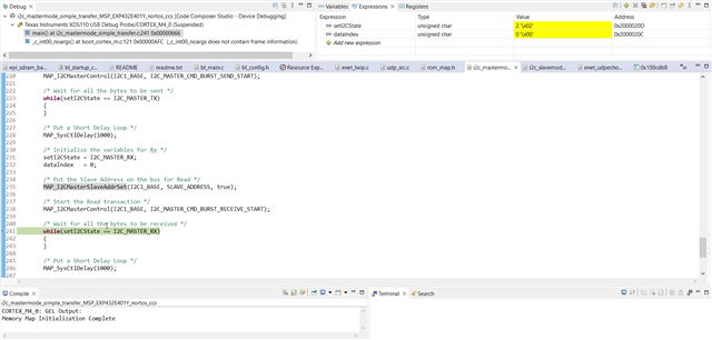
Hi, I am trying to learn how to configure I2C2 for PN4 and PN5 pins, I have slaves which i have to read and write.
Could you help in configuring for same.

I have tried examples from resource explorer, followed same steps but could not do for above pins.

  • Hi,

      Which example are you referring to?

      If you are using non-RTOS bare-metal example such as the i2c_mastermode_simple_transfer_MSP_EXP432E401Y_nortos_ccs, then you would need to change all references from I2C1 to I2C2. You would also need to change the pinmuxing. See below snippet of code for pinmux configuration. Again, yuou will need to go through the entire example source code to change everywhere you see I2C1 to I2C2. 

    FROM:

    /* Enable clocks to GPIO Port G and configure pins as I2C */
    MAP_SysCtlPeripheralEnable(SYSCTL_PERIPH_GPIOG);
    while(!(MAP_SysCtlPeripheralReady(SYSCTL_PERIPH_GPIOG)))
    {
    }

    MAP_GPIOPinConfigure(GPIO_PG0_I2C1SCL);
    MAP_GPIOPinConfigure(GPIO_PG1_I2C1SDA);
    MAP_GPIOPinTypeI2C(GPIO_PORTG_BASE, GPIO_PIN_1);
    MAP_GPIOPinTypeI2CSCL(GPIO_PORTG_BASE, GPIO_PIN_0);

    /* Since there are no board pull up's we shall enable the weak internal
    * pull up */
    GPIOG->PUR |= (GPIO_PIN_1 | GPIO_PIN_0);

    TO:

    /* Enable clocks to GPIO Port N and configure pins as I2C */
    MAP_SysCtlPeripheralEnable(SYSCTL_PERIPH_GPION);
    while(!(MAP_SysCtlPeripheralReady(SYSCTL_PERIPH_GPION)))
    {
    }

    MAP_GPIOPinConfigure(GPIO_PN5_I2C2SCL);
    MAP_GPIOPinConfigure(GPIO_PN4_I2C2SDA);
    MAP_GPIOPinTypeI2C(GPIO_PORTN_BASE, GPIO_PIN_4);
    MAP_GPIOPinTypeI2CSCL(GPIO_PORTN_BASE, GPIO_PIN_5);

    /* Since there are no board pull up's we shall enable the weak internal
    * pull up */
    GPION->PUR |= (GPIO_PIN_5 | GPIO_PIN_4);

    If you are using the SimpleLink SDK with TI-RTOS, then you can reference the i2ctmp_MSP_EXP432E401Y_tirtos_ccs example. This example uses I2C2 module already and the pinmux is configured using the Sysconfig tool. 

  • Hi,

    I have changed I2C1 to I2C2 in

    i2c_mastermode_simple_transfer_MSP_EXP432E401Y_nortos_ccs and flashed in master

    I have changed I2C1 to I2C2 in

    i2c_slavemode_simple_transfer_MSP_EXP432E401Y_nortos_ccs and flashed in slave,

    I see no communication between MCU's.

    I have connected only SDA and SCL lines between MCU's. Am i doing something wrong..?

  • Hi Charles,

    I have tried using same code as in resource explorer i2c_mastermode_simple_transfer_MSP_EXP432E401Y_nortos_ccs and i2c_slavemode_simple_transfer_MSP_EXP432E401Y_nortos_ccs, with PG0 and PG1 pins for I2C.

    I see no communcation between MCU's.

    While suspending the debug, it is stopping at the below point

    But while checking the same with oscilloscope, SCL is as below but couldn't get any waveform for SDA

  • Some questions:

    - Do you have the pullup resistors on both the SCL and SDA buses?

    - If you run both the master and the slave examples as is without any modification, do you see a difference? If it works as is then it must be something in your modified code for I2C2 that is not properly configured. 

  • Internal pull-up resistors have been used.

    Codes for both Master and slave have been used directly from resource explorer for I2C1( i.e., PG0 & PG1).

  • Internal pull-up resistors have been used.

    You cannot rely on internal pull. You must use external pullup.