This thread has been locked.

If you have a related question, please click the "Ask a related question" button in the top right corner. The newly created question will be automatically linked to this question.

MSPM0G3507: Higher error in frequency measurement when activating Frequency Loop Correction (FLC)

Part Number: MSPM0G3507
Other Parts Discussed in Thread: SYSCONFIG

Tool/software:

Hi,

In my application, in order to improve the frequency measurement stability with temperature variations I enabled the Frequency Correction Loop functionality by calling this function right after the main code start.

DL_SYSCTL_enableSYSOSCFCL();

At hardware level,  the frequency correction loop (FCL) circuit utilizes an external 100-kΩ resistor, populated between the ROSC pin and VSS. I assembled it.

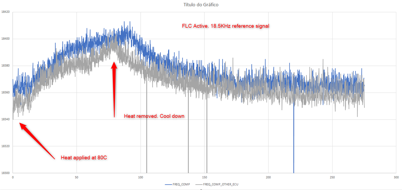
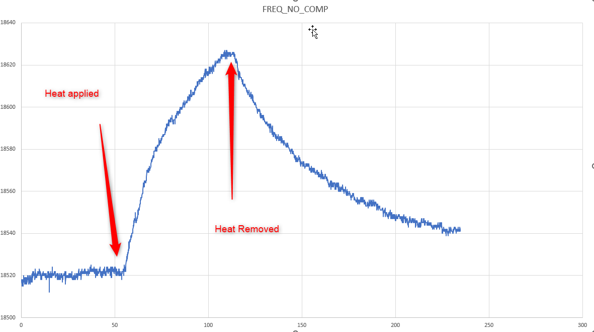
To verify the functionality, I exposed the MCU to a heat gun configured to 80'C and observed the behavior of the measurement of a fixed frequency input channel with FCL active and without.

What I observed was:

-FCL reduces significantly the measurement variation with the heating process comparatively to the scenario without its activation.

-FCL introduces a relevant offset at ambient temperature frequency measurement comparatively to the condition where it is not active (around140Hz)

I performed this test with two different systems, with the same result.

What is the maximum admissible tolerance for this resistor? Are these results in line with a core frequency of 32MHz and a 1% tolerance resistor?

Thanks for the support

  • Hi Romulo,

    We recommend the usage of a 0.1% tolerance resistor for ROSC. The data you've posted here is the only data with this ROSC value that I've seen so I could not comment whether the behavior you are seeing is expected.

  • Hi,

    Regarding the configuration procedure, nothing more is necessary other than use that system call once in the main function right?

    I will change the ros reisstor to check the impact. 

    thanks

  • You will also need to initialize the peripheral analog function for the ROSC pin using the below function. 

    DL_GPIO_initPeripheralAnalogFunction();
    This function, combined with the DL_SYSCTL_enableSYSOSCFCL(); function, will allow proper usage of the FCL.
     
  • Good morning,

    I had the opportunity to test your recomendations but unfortunately it did not resolve my problem.

    Following i will state the tests i did and what i found:

    Do the Peripheral init analog function and enable the SysOSCFCL().

    With a 100kohm 1% tolerance i get a difference of about 12Hz (0.7%) in my measured frequency 1600KHZ

    With a 100kohm 0.1% tolerance i get about the same value as above in my measured frequency 1600KHZ.

    With a 82Kohm resistor i get about the same value as initially. ( this test was just to check the impact of the ROS resistor in this mechanism)

    It seems that whatever resistor i put there, there is no improvement on the compensation mechanism.

    What i find strange is that if i just dont enable the FCL mechanism, my error at ambient temperature in this same measurement is around 1hz. However, the drift with temperature is higher as comparing with the scenario where i enable the FCL.

    What can i be doing wrong to not achieving a compensated frequency measurement at ambient temperature.

    Thanks

  • Hi Romulo,

    I'd encourage you to check the graph in section 7.9.1.1 of our datasheet to compare the accuracy you are seeing to the accuracy we specify across temperatures.

    I'd also like to ask which clock you are outputting and with which dividers? Currently I am questioning whether the accuracy and values you are seeing are outside of our typical range. 

  • Ill do that,

    however my previous questions were not directly answered?

    Is it suposed that the FCL works in such way when i just put a 82K resistor instead the 100K?

    Does FCL solely stabilizes the clock over temperature but not improves its accuracy to a defined reference? I wonder why without FCL active i have measurements closer to my reference value.

    The values i'm obtaining are relative to a Input capture based functionality to measure the time between two consecutive edges.

    i'm using 32Mhz clock with a system clock divider of 1 as reference to the peripherals

  • Sorry I missed that one in my previous response. 

    We do specify a 100kOhm resistor connected to ROSC for the FCL functionality. While I do not know the exact internal workings of ROSC and the FCL, I would not expect the behavior to be exactly the same when using the 82hOhm resistor. I'll see if I can find some more specific information on that from design to try to get an idea of why you are observing this.

    The FCL system is used to improve SYSOSC accuracy in general, and to reduce the change in accuracy across temperature. I think the table I mentioned above does a much better job than I can of explaining the expected behavior. So at ambient temperature I would expect that you'd see higher accuracy with FCL than without. Why you'd see this behavior, I think after a conversation with design I will better be able to answer that question.

    Also, to be clear, could you elaborate a little more on your test set-up here? I'm not sure I am understanding correctly but are you saying that you are using the MSPM0's internal input capture to measure the time between two edges? Maybe some images of the MSPM0 settings in Sysconfig (if you are using it) would help me a bit to understand your implementation better.

  • Hi,

    Did you manage to get more feedback from design team regarding this behavior related with the unexpected behavior with a complete out of range resistor for this calibration procedure?

    We are not using sysconfig in our implementation. However if it clarifies better my setup i will simplify it as:

    1)Use a 1850Hz pwm signal with fixed frequency and 50% duty cycle connected to an input capture port.

    2)Get the counts value from the configured timer that measures the time between two consecutive interrupts (half period of the pwm signal. 

    3)Given the configuration of the timer that supports the input capture peripheral, convert the timer counts into a time value or pwm signal full period frequency.

    4)Without FCL, at ambient temperature before applying heat disturbance,I measured it as 1852.0Hz

    5)With FCL active, at ambient temperature before applying heat disturbance, I measured 1836.0Hz.

    Once again, why is FCL introducing a higher error already at ambient temperature?

    Why even with a 80Kohm resistor (recomended 100Kohm 0.1%), i get the same behavior when I activate this compensation mechanism?

    Thanks

  • I am still waiting on word back from the design team. I've had to ping a few different resources to get infromation on this. Sorry for the delay.

    Are you generating the PWM using an external device, then just connecting to one of the MSPM0's capture compare pins? Then using the count value as the timing mechanism for the PWM rise and fall?

    To give you a preliminary answer, the FCL + ROSC combo are instituting a feedback loop for SYSOSC to help keep the frequency steadier across temperature. Given that we are adding this feedback loop to a system, it does not surprise me that the feedback introduces some offset. A 0.7% offset does not seem that large to me, especially given the indirect method of measuring the SYSOSC frequency. If you are concerned with the offset and accuracy of SYSOSC across temperature, I would recommend that you test the frequency variation by using the clock output functionality and simply probing the clock out pin to directly measure SYSOSC. This will give a more direct view of the error, temperature tolerance, and it will then open up the possibilities for inserting corrections to timing where they are needed.

  • Hi Romulo,

    Have you performed any manual / user trimming of SYSOSC on the device? If so, was this done each time you changed the ROSC resistor?

    Additionally, based on previous responses it seems that you are using your own example but to be sure, what software are you using for this test? Could you paste your program here using the insert-> code feature of E2E?