This thread has been locked.

If you have a related question, please click the "Ask a related question" button in the top right corner. The newly created question will be automatically linked to this question.

MSPM0L1306: MSPM0L1306_External clock input for timer comparison is output from the microcontroller

Part Number: MSPM0L1306

Tool/software:

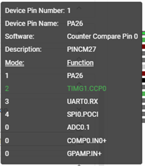
As shown in the attached image, Pin1/PA26 is being used as "TIMG1.CCP0".
And, a 40 kHz external clock is input to Pin1/PA26, but is it possible to output the external clock input to Pin1/PA26 from the microcontroller without dividing it?
Because other pins cannot be used as inputs, it is a must that Pin1/PA26 is set as "TIMG1.CCP0", an external clock is input, and that external clock is then output from the microcontroller.

  • Hey Ryota,

    I didn't understand your question.  Are you trying to input a 40 kHz signal into the timer?  And then you want this same signal output on another pin?  Does the output clock have to be exactly in phase with this input clock? 

    Taking in a 40 kHz signal can be done and outputting a 40kHz square wave can be done, but it seems like this is probably an over simplification of what you want.  

    Can you please give us some more context on what you need the system to do and then we can help you brainstorm a solution?  

    Thanks,

    JD  

  • "Are you trying to input a 40 kHz signal into the timer?"

    → Yes, I want to input a 40 kHz square wave from the outside into the timer as a comparison trigger.

    "you want this same signal output on another pin?"

    → Yes, I want to output the same signal from another pin.

    "Does the output clock have to be exactly in phase with this input clock?"

    → It doesn't have to be in phase, but it would be helpful if you could tell me both in-phase and out-of-phase output.

  • Hey Ryota,

    I am struggling a bit to find an easy way to route the signal to two other pins without CPU intervention.  You can configure the pin as a GPIO input, and have the clock edges on it trigger both the timer and GPIO events via the Event subsystem using channel 3, (1:2 split).  But I think you would only want to trigger the timer on one edge while you'd want to trigger the output GPIO on both input clock edges.  I haven't found a clever way to trigger both through the same event configurations.  

    Would it be okay if the timer just increments on both rising and falling edges?  IE: the timer just counts at 2x the frequency?  

    If not, then I think you may need to configure the pin as an gpio input, set an interrupt on both edges to recreate the output signal, and increment the timer in software only on one edge.

    Hope this helps.

    Thanks,

    JD