This thread has been locked.

If you have a related question, please click the "Ask a related question" button in the top right corner. The newly created question will be automatically linked to this question.

EK-TM4C1294XL: How to use the Bootloader on EK-TM4C1294XL

Part Number: EK-TM4C1294XL


Tool/software:

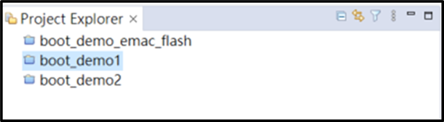
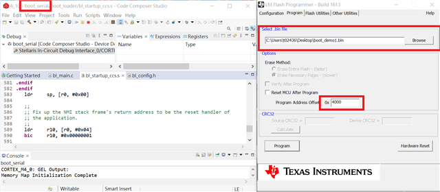
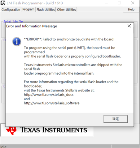
I would like to ask about the TI EK-TM4C1294XL evaluation board and how to use the Bootloader (Uart Update) mechanism. Currently, the problem we encounter is that we use the three bootloader examples provided by TI SDK as shown below. We want to directly use the bootloader examples to design other functions of the MCU. It was found that every time the MCU is restarted, it will directly enter the Bootloader mode instead of running the functions we need and then entering the Bootloader mode. This prevents us from functionally designing the Bootloader architecture.

  • Hi Jeremy,

      Did you first load the boot_serial (the booloader)? The bootloader which is to be loaded via JTAG will reside at 0x0. After the bootloader is running, it will download the example firmware (boot_demo1 or boot_demo2) through the UART interface. These example applications reside at 0x4000. Once the example is running, it is under the application's control to jump back to the bootloader (e.g. pressing SW1) if needed in order to reload the firmware again. At every reset cycle, the bootloader first finds out if there is a valid application by checking if there is a valid stack pointer and reset vector at 0x4000. If there is already a valid application, the bootloader simply jumps to the application to run the application. Refer to the below steps.

      1 Load the boot_serial to the flash using CCS or LM flash programmer.

       2. Run the boot_serial program. 

       3. In LM flash programmer change to manual mode to select UART bootloading. Make sure you select the correct COM port. Go to the Windows device manager to find out which COM port is enumerated. Another important thing is to make sure in your Port setting for the COM port in your Windows, it must have the matching baudrate which is 115200, no parity and 1 stop bit. Below COM11 is for my machine. Your machine will have a different COM port. 

     4 Go the program tab and make sure enter the correct offset address which is 0x4000. Hit the program button and you will see the transfer starts and finished with the number of bytes transferred in the bottom. 

    5. You can press the reset button on the board.. You should see the LED blinking. 

    6. Press the SW1. The LED should stop blinking as it has jumped to the bootloader

    7. Go to step 4 again and hit the program button to load another program like the boot_demo2 

  • Hi Charles Tsai
    We followed your method but errors occurred. Is there anything we need to pay attention to?
    1. Use boot_serial for JTAG to be loaded
    2. Then use LM flash programmer to load it through Uart.

    1.

    2.