

Tool/software:
How to Configuration Flash Memory on EK-TM4C1294XL,I want to divide my FLASH into Flash blocks to store Data address and access

This thread has been locked.
If you have a related question, please click the "Ask a related question" button in the top right corner. The newly created question will be automatically linked to this question.
Tool/software:
How to Configuration Flash Memory on EK-TM4C1294XL,I want to divide my FLASH into Flash blocks to store Data address and access
Hi,
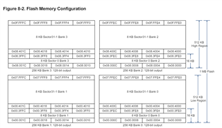
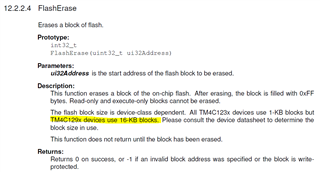
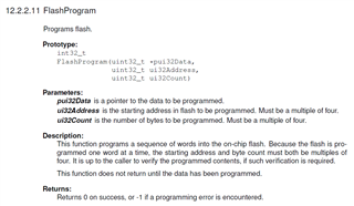
Each block is 16kB. Therefore, you can place your data at a 16kB boundary. Refer to the FlashProgram and FlashErase APIs to program and erase data in the flash.
Here is a simple example.
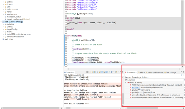
uint32_t pui32Data[2];
//
// Erase a block of the flash.
//
FlashErase(0x800);
//
// Program some data into the newly erased block of the flash.
//
pui32Data[0] = 0x12345678;
pui32Data[1] = 0x56789abc;
FlashProgram(pui32Data, 0x800, sizeof(pui32Data));

Hi Charles Tsal
We have followed your example and referred to other articles you responded to
e2e.ti.com/.../sw-dk-tm4c129x-tm4c129-internal- memory-read-write
1.We have a problem here, which is how to observe my Flash location in the IDE of Code Composer Studio. We need to determine whether it is written correctly.
2.How to use Here is a simple example. Do you need to include a specific function library?
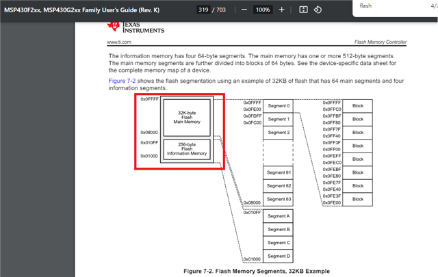
3.Is the Flash splitting method different between EK-TM4C1294XL and MSP430F2xx?
4.Does EK-TM4C1294XL need to define its own blocks or does the Flash in MSP430F2xx have Main Memory and Information Memory?
5.How to use EEPROM? Is it the same as Flash? I need to use Uart to write and read data.
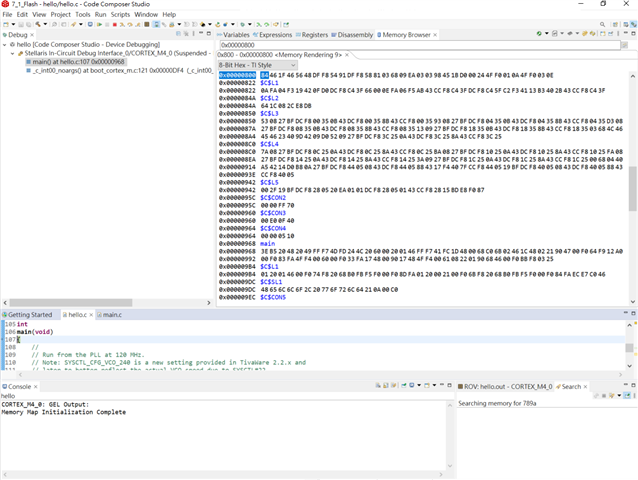

1.We have a problem here, which is how to observe my Flash location in the IDE of Code Composer Studio. We need to determine whether it is written correctly.
2.How to use Here is a simple example. Do you need to include a specific function library?
Hi,
Sorry, the example shown in the user's guide is not ideal. The reason is that the address to program is 0x800. This is normally an address where you main code will reside depending on how large your main program is. Therefore, I would expect at 0x800 you would already have some code in it. I will suggest you try out a different address where you main code does not reside. Perhaps you can try an address like 0x8000 or 0xC0000 if you are sure you don't have anything there. First program your source code to the flash and examine the address 0x8000. It is supposed to be 0xFFFFFFFF in an erased state. Next program this location with some value and re-examine this address using Memory Window to see if it changes value.
3.Is the Flash splitting method different between EK-TM4C1294XL and MSP430F2xx?
4.Does EK-TM4C1294XL need to define its own blocks or does the Flash in MSP430F2xx have Main Memory and Information Memory?
I don't support MSP432F2xx and therefore do not know how the flash is organized in that MCU. I don't think the flash organization will be the same. You will need to read the MSP432F2xx datasheet about how they organize the flash and their architecture.
5.How to use EEPROM? Is it the same as Flash? I need to use Uart to write and read data.
EEprom is an entirely different flash block that is emulated to behave like a EEprom in terms of read and write operations. Please refer to the EEprom operation in the Peripheral Driver user's guide and also the datasheet on its architecture of operations.
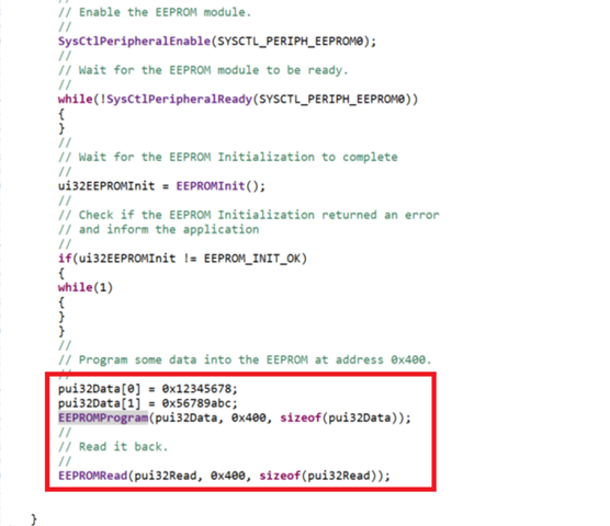
9.3 Programming Example
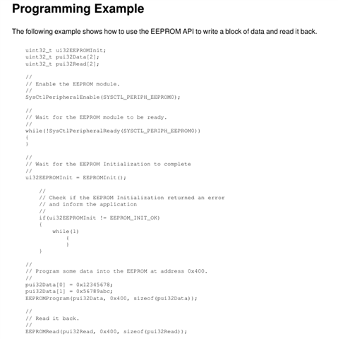
The following example shows how to use the EEPROM API to write a block of data and read it back.
uint32_t ui32EEPROMInit;
uint32_t pui32Data[2];
uint32_t pui32Read[2];
//
// Enable the EEPROM module.
//
SysCtlPeripheralEnable(SYSCTL_PERIPH_EEPROM0);
//
// Wait for the EEPROM module to be ready.
//
while(!SysCtlPeripheralReady(SYSCTL_PERIPH_EEPROM0))
{
}
//
// Wait for the EEPROM Initialization to complete
//
ui32EEPROMInit = EEPROMInit();
//
// Check if the EEPROM Initialization returned an error
// and inform the application
//
if(ui32EEPROMInit != EEPROM_INIT_OK)
{
while(1)
{
}
}
//
// Program some data into the EEPROM at address 0x400.
//
pui32Data[0] = 0x12345678;
pui32Data[1] = 0x56789abc;
EEPROMProgram(pui32Data, 0x400, sizeof(pui32Data));
//
// Read it back.
//
EEPROMRead(pui32Read, 0x400, sizeof(pui32Read));
Please also be aware of some known errata associated with the EEprom. Refer to the errata.
HI Charles Tsai
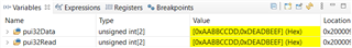
1.I used the EEPROM sample program you provided and after running it, I used Memory Browser to observe the location of address 0x400 and found that the location of address 0x400 was not written to the EEPROM.
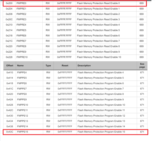
2.6KB EEPROM address 0x200 - 0x43C ??
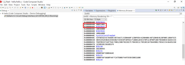
1.I used the EEPROM sample program you provided and after running it, I used Memory Browser to observe the location of address 0x400 and found that the location of address 0x400 was not written to the EEPROM.
2.6KB EEPROM address 0x200 - 0x43C ??
No, EEProm memory is not memory mapped. You cannot use the memory browser to view the EEProm content. You will need to read it using EEPROMRead() API only.
HI Charles Tsai Thanks for your assistance
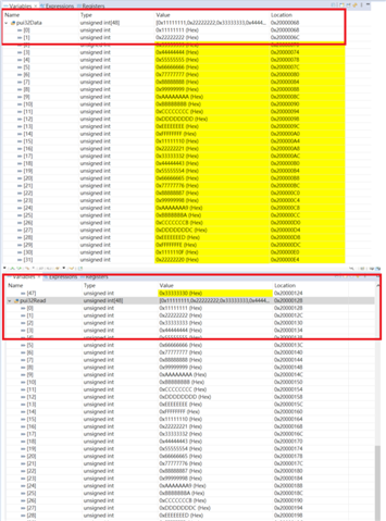
1.I have been able to run the example normally to write data to EEPROM and use Uart to read data from EEPROM.Refer example to e2echina.ti.com/.../ccs-ek-tm4c1294xl-eeprom But I want to write Data into 96 blocks using EEPROM, but the current program cannot write to 96 and can only write to 48 at most and read it back. I want to ask if there is a problem with my program or if I need to use another one. address
2.Is there any other TI tool that can help us view the location of the EEPROM and its data content?
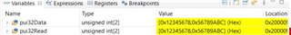
3.I would like to ask if Variables can observe the address and value of my EEPROM.
//*****************************************************************************
//
// hello.c - Simple hello world example.
//
// Copyright (c) 2013-2020 Texas Instruments Incorporated. All rights reserved.
// Software License Agreement
//
// Texas Instruments (TI) is supplying this software for use solely and
// exclusively on TI's microcontroller products. The software is owned by
// TI and/or its suppliers, and is protected under applicable copyright
// laws. You may not combine this software with "viral" open-source
// software in order to form a larger program.
//
// THIS SOFTWARE IS PROVIDED "AS IS" AND WITH ALL FAULTS.
// NO WARRANTIES, WHETHER EXPRESS, IMPLIED OR STATUTORY, INCLUDING, BUT
// NOT LIMITED TO, IMPLIED WARRANTIES OF MERCHANTABILITY AND FITNESS FOR
// A PARTICULAR PURPOSE APPLY TO THIS SOFTWARE. TI SHALL NOT, UNDER ANY
// CIRCUMSTANCES, BE LIABLE FOR SPECIAL, INCIDENTAL, OR CONSEQUENTIAL
// DAMAGES, FOR ANY REASON WHATSOEVER.
//
// This is part of revision 2.2.0.295 of the EK-TM4C1294XL Firmware Package.
//
//*****************************************************************************
#include <stdint.h>
#include <stdbool.h>
#include "inc/hw_memmap.h"
#include "inc/hw_types.h"
#include "driverlib/gpio.h"
#include "drivers/pinout.h"
#include "driverlib/pin_map.h"
#include "driverlib/rom.h"
#include "driverlib/rom_map.h"
#include "driverlib/sysctl.h"
#include "driverlib/uart.h"
#include "utils/uartstdio.h"
#include "driverlib/eeprom.h"
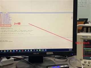
#define j 48 // only 48
//*****************************************************************************
//
//! \addtogroup example_list
//! <h1>Hello World (hello)</h1>
//!
//! A very simple ``hello world'' example. It simply displays ``Hello World!''
//! on the UART and is a starting point for more complicated applications.
//!
//! Open a terminal with 115,200 8-N-1 to see the output for this demo.
//
//*****************************************************************************
//*****************************************************************************
//
// System clock rate in Hz.
//
//*****************************************************************************
uint32_t g_ui32SysClock;
int i;
//*****************************************************************************
//
// The error routine that is called if the driver library encounters an error.
//
//*****************************************************************************
#ifdef DEBUG
void
__error__(char *pcFilename, uint32_t ui32Line)
{
}
#endif
//*****************************************************************************
//
// Configure the UART and its pins. This must be called before UARTprintf().
//
//*****************************************************************************
void
UARTSend(const uint8_t *pui8Buffer, uint32_t ui32Count)
{
//
// Loop while there are more characters to send.
//
while(ui32Count--)
{
//
// Write the next character to the UART.
//
MAP_UARTCharPutNonBlocking(UART0_BASE, *pui8Buffer++);
}
}
void
ConfigureUART(void)
{
//
// Enable the GPIO Peripheral used by the UART.
//
MAP_SysCtlPeripheralEnable(SYSCTL_PERIPH_GPIOA);
//
// Enable UART0
//
MAP_SysCtlPeripheralEnable(SYSCTL_PERIPH_UART0);
//
// Configure GPIO Pins for UART mode.
//
MAP_GPIOPinConfigure(GPIO_PA0_U0RX);
MAP_GPIOPinConfigure(GPIO_PA1_U0TX);
MAP_GPIOPinTypeUART(GPIO_PORTA_BASE, GPIO_PIN_0 | GPIO_PIN_1);
//
// Initialize the UART for console I/O.
//
UARTStdioConfig(0, 115200, g_ui32SysClock);
}
//*****************************************************************************
//
// Print "Hello World!" to the UART on the Intelligent UART Module.
//
//*****************************************************************************
int
main(void)
{
//
// Run from the PLL at 120 MHz.
// Note: SYSCTL_CFG_VCO_240 is a new setting provided in TivaWare 2.2.x and
// later to better reflect the actual VCO speed due to SYSCTL#22.
//
g_ui32SysClock = MAP_SysCtlClockFreqSet((SYSCTL_XTAL_25MHZ |
SYSCTL_OSC_MAIN |
SYSCTL_USE_PLL |
SYSCTL_CFG_VCO_240), 120000000);
//
// Configure the device pins.
//
PinoutSet(false, false);
//
// Enable the GPIO pins for the LED D1 (PN1).
//
MAP_GPIOPinTypeGPIOOutput(GPIO_PORTN_BASE, GPIO_PIN_1);
//
// Initialize the UART.
//
ConfigureUART();
//
// Hello!
//
//
// We are finished. Hang around flashing D1.
//
while(1)
{
uint32_t e2block;
uint32_t ui32EEPROMInit;
uint32_t pui32Data[j];
uint32_t pui32Read[j];
//
// Enable the EEPROM module.
//
SysCtlPeripheralEnable(SYSCTL_PERIPH_EEPROM0);
//
// Wait for the EEPROM module to be ready.
//
while(!SysCtlPeripheralReady(SYSCTL_PERIPH_EEPROM0))
{
}
//
// Wait for the EEPROM Initialization to complete
//
ui32EEPROMInit = EEPROMInit();
//
// Check if the EEPROM Initialization returned an error
// and inform the application
//
if(ui32EEPROMInit != EEPROM_INIT_OK)
{
while(1)
{
}
}
//
// Program some data into the EEPROM at address 0x400.
//
SysCtlDelay(50000000);
for(i=0;i<j;i++) {
pui32Data[i] = (i + 1) * 0x11111111; //
};
EEPROMProgram(pui32Data,0x400, sizeof(pui32Data)); //0x17FC
EEPROMRead(pui32Read, 0x400, sizeof(pui32Read));
for (i=0;i<j;i++) {
UARTprintf("number: %d\n", i );
UARTprintf("Data read from EEPROM: %x\n", pui32Read[i]); //
SysCtlDelay(30000000);
};
//UARTprintf("Data read from EEPROM SIze: %d\n",EEPROMSizeGet());
}
}
Hi,
You define j to be 48 in your program. Look at your program at line 39 where you wrote:
#define j 48 // only 48
HI Charles Tsai:
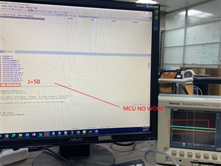
1.The definition program problem you mentioned has been tested and it can only work if it is J input to a 48 MCU.If the MCU exceeds 48, for example, 50, it will not operate. The waveforms of my program and oscilloscope are as shown below.
2.I would like to ask if the positions will be automatically sorted. I refer to Compiler/EK-TM4C1294XL: How to read two consecutive locations of EEPROM into a structure. This article found that EEPROM_ADDRESS needs to be defined starting from 0x0000 and the offset will be increased each time. I want to ask if it is necessary. Define 96 addresses from (0x000...0x095) or define one for every four addresses (0x000....0x17c)
Instead of using (0x400) directly for automatic sorting, I tried to use his method but it still failed.
Hi,
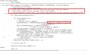
EEprom offset address 0x400 corresponds to block #16. EEprom address 0xC80 corresponds to block #50 and address 0x1800 corresponds to block #96.
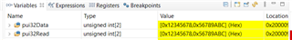
I use the below code to do some writes to EEprom and single step the code and I'm getting correct data.
// // Program some data into the EEPROM at address 0x400. // pui32Data[0] = 0x12345678; pui32Data[1] = 0x56789abc; EEPROMProgram(pui32Data, 0x400, sizeof(pui32Data)); // // Read it back. // EEPROMRead(pui32Read, 0x400, sizeof(pui32Read));
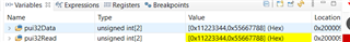
pui32Data[0] = 0x11223344; pui32Data[1] = 0x55667788; EEPROMProgram(pui32Data, 0xc80, sizeof(pui32Data)); // // Read it back. // EEPROMRead(pui32Read, 0xc80, sizeof(pui32Read));
pui32Data[0] = 0xAABBCCDD; pui32Data[1] = 0xDEADBEEF; EEPROMProgram(pui32Data, 0x1800, sizeof(pui32Data)); // // Read it back. // EEPROMRead(pui32Read, 0x1800, sizeof(pui32Read));
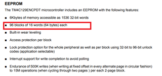
Refer to the datasheet on the organization of EEprom. There are 96 blocks and each block is 16 words or 64 bytes. Each word is equal to 4 bytes.
8.2.4.1 Functional Description
The EEPROM module provides a well-defined register interface to support accesses to the EEPROM
with both a random access style of read and write as well as a rolling or sequential access scheme.
A protection mechanism allows locking EEPROM blocks to prevent writes under a set of
circumstances as well as reads under the same or different circumstances. The password model
allows the application to lock one or more EEPROM blocks to control access on 16-word boundaries.
Blocks
There are 96 blocks of 16 words each in the EEPROM. These are readable and writable as words.
Bytes and half-words can be read, and these accesses do not have to occur on a word boundary.
The entire word is read and any unneeded data is simply ignored. The EEPROM blocks are writable
only on a word basis. To write a byte, it is necessary to read the word value, modify the appropriate
byte, and write the word back.
Each block is addressable as an offset within the EEPROM, using a block select register. Each
word is offset addressable within the selected block.
HI Charles Tsai:
1.Program 1
What we currently understand means that an EEprom address is defined every 64 bytes. Our program will start from address 0x000 and define it every 0x040 until the 96 blocks address is 0x1800.Is the EEPROM address and data defined in this way correct?
2.Program 2
If the program defines EEPROM addresses and data for more than 96 blocks, will there be any problems?
3.UARTCharGetNonBlocking cannot call UARTprintf
Program 1
//*****************************************************************************
//
// hello.c - Simple hello world example.
//
// Copyright (c) 2013-2020 Texas Instruments Incorporated.  All rights reserved.
// Software License Agreement
//
// Texas Instruments (TI) is supplying this software for use solely and
// exclusively on TI's microcontroller products. The software is owned by
// TI and/or its suppliers, and is protected under applicable copyright
// laws. You may not combine this software with "viral" open-source
// software in order to form a larger program.
//
// THIS SOFTWARE IS PROVIDED "AS IS" AND WITH ALL FAULTS.
// NO WARRANTIES, WHETHER EXPRESS, IMPLIED OR STATUTORY, INCLUDING, BUT
// NOT LIMITED TO, IMPLIED WARRANTIES OF MERCHANTABILITY AND FITNESS FOR
// A PARTICULAR PURPOSE APPLY TO THIS SOFTWARE. TI SHALL NOT, UNDER ANY
// CIRCUMSTANCES, BE LIABLE FOR SPECIAL, INCIDENTAL, OR CONSEQUENTIAL
// DAMAGES, FOR ANY REASON WHATSOEVER.
//
// This is part of revision 2.2.0.295 of the EK-TM4C1294XL Firmware Package.
//
//*****************************************************************************

#include <stdint.h>
#include <stdbool.h>
#include "inc/hw_memmap.h"
#include "inc/hw_types.h"
#include "driverlib/gpio.h"
#include "drivers/pinout.h"
#include "driverlib/pin_map.h"
#include "driverlib/rom.h"
#include "driverlib/rom_map.h"
#include "driverlib/sysctl.h"
#include "driverlib/uart.h"
#include "utils/uartstdio.h"
#include "driverlib/eeprom.h"

#define j  97 // 96
//*****************************************************************************
//
//! \addtogroup example_list
//! <h1>Hello World (hello)</h1>
//!
//! A very simple ``hello world'' example.  It simply displays ``Hello World!''
//! on the UART and is a starting point for more complicated applications.
//!
//! Open a terminal with 115,200 8-N-1 to see the output for this demo.
//
//*****************************************************************************

//*****************************************************************************
//
// System clock rate in Hz.
//
//*****************************************************************************
uint32_t g_ui32SysClock;
uint32_t ui32EEPROMInit, ui32EEPROMStatus;

int i;

//*****************************************************************************
//
// The error routine that is called if the driver library encounters an error.
//
//*****************************************************************************
#ifdef DEBUG
void
__error__(char *pcFilename, uint32_t ui32Line)
{
}
#endif

//*****************************************************************************
//
// Configure the UART and its pins.  This must be called before UARTprintf().
//
//*****************************************************************************

void
UARTSend(const uint8_t *pui8Buffer, uint32_t ui32Count)
{
    //
    // Loop while there are more characters to send.
    //
    while(ui32Count--)
    {
        //
        // Write the next character to the UART.
        //
        MAP_UARTCharPutNonBlocking(UART0_BASE, *pui8Buffer++);
    }
}


void
ConfigureUART(void)
{
    //
    // Enable the GPIO Peripheral used by the UART.
    //
    MAP_SysCtlPeripheralEnable(SYSCTL_PERIPH_GPIOA);

    //
    // Enable UART0
    //
    MAP_SysCtlPeripheralEnable(SYSCTL_PERIPH_UART0);

    //
    // Configure GPIO Pins for UART mode.
    //
    MAP_GPIOPinConfigure(GPIO_PA0_U0RX);
    MAP_GPIOPinConfigure(GPIO_PA1_U0TX);
    MAP_GPIOPinTypeUART(GPIO_PORTA_BASE, GPIO_PIN_0 | GPIO_PIN_1);

    //
    // Initialize the UART for console I/O.
    //
    UARTStdioConfig(0, 115200, g_ui32SysClock);
}

//*****************************************************************************
//
// Print "Hello World!" to the UART on the Intelligent UART Module.
//
//*****************************************************************************
int
main(void)
{
    uint32_t pui32Data[2];
    uint32_t pui32Read[2];
    //
    // Run from the PLL at 120 MHz.
    // Note: SYSCTL_CFG_VCO_240 is a new setting provided in TivaWare 2.2.x and
    // later to better reflect the actual VCO speed due to SYSCTL#22.
    //
    g_ui32SysClock = MAP_SysCtlClockFreqSet((SYSCTL_XTAL_25MHZ |
                                             SYSCTL_OSC_MAIN |
                                             SYSCTL_USE_PLL |
                                             SYSCTL_CFG_VCO_240), 120000000);

    //
    // Configure the device pins.
    //
    PinoutSet(false, false);

    //
    // Enable the GPIO pins for the LED D1 (PN1).
    //
    MAP_GPIOPinTypeGPIOOutput(GPIO_PORTN_BASE, GPIO_PIN_1);

    //
    // Initialize the UART.
    //
    ConfigureUART();

    //
    // Hello!
    //

    //
    // We are finished.  Hang around flashing D1.
    //
    while(1)
    {
        uint32_t  e2block;
        uint32_t ui32EEPROMInit;


        //
        // Enable the EEPROM module.
        //
        SysCtlPeripheralEnable(SYSCTL_PERIPH_EEPROM0);
        //
        // Wait for the EEPROM module to be ready.
        //


        while(!SysCtlPeripheralReady(SYSCTL_PERIPH_EEPROM0))
        {
        }
        //
        // Wait for the EEPROM Initialization to complete
        //
        ui32EEPROMInit = EEPROMInit();
        //
        // Check if the EEPROM Initialization returned an error
        // and inform the application
        //
        if(ui32EEPROMInit != EEPROM_INIT_OK)
        {
        while(1)
        {
        }
        }
        //
        // Program some data into the EEPROM at address 0x400.
        //
        SysCtlDelay(50000000);

            for(i=0;i<j;i++) {
                pui32Data[0] = (i + 1)* 0x11111111;
                pui32Data[1] = (i + 1)* 0x11111111;  //pui32Data[i] = (i + 1) * 0x11111111;
                EEPROMProgram(pui32Data,0x0000+(i*0x40), sizeof(pui32Data));
                //UARTprintf("Write from EEPROM: %d\n", pui32Data[i]);
                while (ui32EEPROMStatus == EEPROM_RC_WORKING){

                }
            };
 //0x17FC
       while (ui32EEPROMStatus == EEPROM_RC_WORKING){
       }


            for (i=0;i<j;i++) {
                UARTprintf("number: %d\n", i );
                //UARTprintf("Data read from EEPROM: %x\n", pui32Read[i]);
                EEPROMRead(pui32Read, 0x0000+(i*0x40), sizeof(pui32Read));
                while (ui32EEPROMStatus == EEPROM_RC_WORKING){
                }
                UARTprintf("Number address:0x %x\n",(i*0x40));
                UARTprintf("Data read from EEPROM: %x\n", pui32Read[i]);
                UARTprintf("Read from EEPROM[0]: %x\n", pui32Read[0]);
                UARTprintf("Read from EEPROM[1]: %x\n", pui32Read[1]);
                SysCtlDelay(20000000);
            };

//        UARTprintf("Data read from EEPROM SIze: %d\n",EEPROMSizeGet());


    }
}
Program 2
//*****************************************************************************
//
// hello.c - Simple hello world example.
//
// Copyright (c) 2013-2020 Texas Instruments Incorporated.  All rights reserved.
// Software License Agreement
//
// Texas Instruments (TI) is supplying this software for use solely and
// exclusively on TI's microcontroller products. The software is owned by
// TI and/or its suppliers, and is protected under applicable copyright
// laws. You may not combine this software with "viral" open-source
// software in order to form a larger program.
//
// THIS SOFTWARE IS PROVIDED "AS IS" AND WITH ALL FAULTS.
// NO WARRANTIES, WHETHER EXPRESS, IMPLIED OR STATUTORY, INCLUDING, BUT
// NOT LIMITED TO, IMPLIED WARRANTIES OF MERCHANTABILITY AND FITNESS FOR
// A PARTICULAR PURPOSE APPLY TO THIS SOFTWARE. TI SHALL NOT, UNDER ANY
// CIRCUMSTANCES, BE LIABLE FOR SPECIAL, INCIDENTAL, OR CONSEQUENTIAL
// DAMAGES, FOR ANY REASON WHATSOEVER.
//
// This is part of revision 2.2.0.295 of the EK-TM4C1294XL Firmware Package.
//
//*****************************************************************************

#include <stdint.h>
#include <stdbool.h>
#include "inc/hw_memmap.h"
#include "inc/hw_types.h"
#include "driverlib/gpio.h"
#include "drivers/pinout.h"
#include "driverlib/pin_map.h"
#include "driverlib/rom.h"
#include "driverlib/rom_map.h"
#include "driverlib/sysctl.h"
#include "driverlib/uart.h"
#include "utils/uartstdio.h"
#include "driverlib/eeprom.h"

#define j  96 // only 48
//*****************************************************************************
//
//! \addtogroup example_list
//! <h1>Hello World (hello)</h1>
//!
//! A very simple ``hello world'' example.  It simply displays ``Hello World!''
//! on the UART and is a starting point for more complicated applications.
//!
//! Open a terminal with 115,200 8-N-1 to see the output for this demo.
//
//*****************************************************************************

//*****************************************************************************
//
// System clock rate in Hz.
//
//*****************************************************************************
uint32_t g_ui32SysClock;
uint32_t ui32EEPROMInit, ui32EEPROMStatus;

int i;

//*****************************************************************************
//
// The error routine that is called if the driver library encounters an error.
//
//*****************************************************************************
#ifdef DEBUG
void
__error__(char *pcFilename, uint32_t ui32Line)
{
}
#endif

//*****************************************************************************
//
// Configure the UART and its pins.  This must be called before UARTprintf().
//
//*****************************************************************************

void
UARTSend(const uint8_t *pui8Buffer, uint32_t ui32Count)
{
    //
    // Loop while there are more characters to send.
    //
    while(ui32Count--)
    {
        //
        // Write the next character to the UART.
        //
        MAP_UARTCharPutNonBlocking(UART0_BASE, *pui8Buffer++);
    }
}


void
ConfigureUART(void)
{
    //
    // Enable the GPIO Peripheral used by the UART.
    //
    MAP_SysCtlPeripheralEnable(SYSCTL_PERIPH_GPIOA);

    //
    // Enable UART0
    //
    MAP_SysCtlPeripheralEnable(SYSCTL_PERIPH_UART0);

    //
    // Configure GPIO Pins for UART mode.
    //
    MAP_GPIOPinConfigure(GPIO_PA0_U0RX);
    MAP_GPIOPinConfigure(GPIO_PA1_U0TX);
    MAP_GPIOPinTypeUART(GPIO_PORTA_BASE, GPIO_PIN_0 | GPIO_PIN_1);

    //
    // Initialize the UART for console I/O.
    //
    UARTStdioConfig(0, 115200, g_ui32SysClock);
}

//*****************************************************************************
//
// Print "Hello World!" to the UART on the Intelligent UART Module.
//
//*****************************************************************************
int
main(void)
{
    uint32_t pui32Data[2];
    uint32_t pui32Read[2];
    //
    // Run from the PLL at 120 MHz.
    // Note: SYSCTL_CFG_VCO_240 is a new setting provided in TivaWare 2.2.x and
    // later to better reflect the actual VCO speed due to SYSCTL#22.
    //
    g_ui32SysClock = MAP_SysCtlClockFreqSet((SYSCTL_XTAL_25MHZ |
                                             SYSCTL_OSC_MAIN |
                                             SYSCTL_USE_PLL |
                                             SYSCTL_CFG_VCO_240), 120000000);

    //
    // Configure the device pins.
    //
    PinoutSet(false, false);

    //
    // Enable the GPIO pins for the LED D1 (PN1).
    //
    MAP_GPIOPinTypeGPIOOutput(GPIO_PORTN_BASE, GPIO_PIN_1);

    //
    // Initialize the UART.
    //
    ConfigureUART();

    //
    // Hello!
    //

    //
    // We are finished.  Hang around flashing D1.
    //
    while(1)
    {
        uint32_t  e2block;
        uint32_t ui32EEPROMInit;


        //
        // Enable the EEPROM module.
        //
        SysCtlPeripheralEnable(SYSCTL_PERIPH_EEPROM0);
        //
        // Wait for the EEPROM module to be ready.
        //


        while(!SysCtlPeripheralReady(SYSCTL_PERIPH_EEPROM0))
        {
        }
        //
        // Wait for the EEPROM Initialization to complete
        //
        ui32EEPROMInit = EEPROMInit();
        //
        // Check if the EEPROM Initialization returned an error
        // and inform the application
        //
        if(ui32EEPROMInit != EEPROM_INIT_OK)
        {

        }
        //
        // Program some data into the EEPROM at address 0x400.
        //
        // Program some data into the EEPROM at address 0x400.
        //
        pui32Data[0] = 0x12345678;
        pui32Data[1] = 0x56789abc;
        EEPROMProgram(pui32Data, 0x400, sizeof(pui32Data));
        //
        // Read it back.
        //
        EEPROMRead(pui32Read, 0x400, sizeof(pui32Read));

        pui32Data[0] = 0x11223344;
        pui32Data[1] = 0x55667788;
        EEPROMProgram(pui32Data, 0xc80, sizeof(pui32Data));
        //
        // Read it back.
        //
        EEPROMRead(pui32Read, 0xc80, sizeof(pui32Read));

        pui32Data[0] = 0xAABBCCDD;
        pui32Data[1] = 0xDEADBEEF;
        EEPROMProgram(pui32Data, 0x1800, sizeof(pui32Data));
        //
        // Read it back.
        //
        EEPROMRead(pui32Read, 0x1800, sizeof(pui32Read));

        pui32Data[0] = 0xDDDDDDDD;
        pui32Data[1] = 0xDEADBEEF;
        EEPROMProgram(pui32Data, 0x1840, sizeof(pui32Data));
        //
        // Read it back.
        //
        EEPROMRead(pui32Read, 0x1840, sizeof(pui32Read));

        pui32Data[0] = 0xCCCCCCCC;
        pui32Data[1] = 0xDEADBEEF;
        EEPROMProgram(pui32Data, 0x1880, sizeof(pui32Data));
        //
        // Read it back.
        //
        EEPROMRead(pui32Read, 0x1880, sizeof(pui32Read));


    }
}
1.Program 1
What we currently understand means that an EEprom address is defined every 64 bytes. Our program will start from address 0x000 and define it every 0x040 until the 96 blocks address is 0x1800.Is the EEPROM address and data defined in this way correct?
Correct, each EEprom block is 16 words wide which means 64 bytes.
2.Program 2
If the program defines EEPROM addresses and data for more than 96 blocks, will there be any problems?
I don't know what will happen if you define more than 96 blocks. I will advice you not exceed 96 blocks (which is the maximum as implemented on the MCU) as it will be an unknown behavior.
3.UARTCharGetNonBlocking cannot call UARTprintf
I don't understand what you mean. Can you look at the hello example or many other examples where UARTPrintf() is called. Please try the hello example first and get a feel on how it works and prints to the terminal via the COM port.
HI Charles Tsai:
1.We have some data that is transmitted in 1byte. I would like to ask if eeprom can write data in 1byte instead of word.
2.in the example, only 16 hexadecimal numbers are used, which means that only 16 words are used. I would like to ask Can 16 hexadecimal 64 bytes be used?
For example, uint32_t change to uint8 or Could you please tell me which of the following 3 definitions are used?
  1.
  pui32Data[0] = 0xAA; // 1byte
  pui32Data[1] = 0xBB; // 2byte
	.
	.
	.
  pui32Data[62] = 0xEE;// 63byte
  pui32Data[63] = 0xFF;// 64byte

  or

  2.
  pui32Data[0] = 0xAAAAA........AAA; //32bytes
  pui32Data[1] = 0xBBBBB........BBB; //32bytes

  or
  3.
  pui32Data[0] = 0xAAAAA..................AAA; //64bytes
Hi Jeremy,
Please find below description.
Blocks
There are 96 blocks of 16 words each in the EEPROM. These are readable and writable as words.
Bytes and half-words can be read, and these accesses do not have to occur on a word boundary.
The entire word is read and any unneeded data is simply ignored. The EEPROM blocks are writable
only on a word basis. To write a byte, it is necessary to read the word value, modify the appropriate
byte, and write the word back.
HI Charles Tsai:
Sorry I do not understand
Program 1
The maximum range of pui32Data can be pui32Data[16] or pui32Data[2]
Can the range of pui32Data be 64byte in pui32Data[0-15]?
The original example is pui32Data[0-1] 8byte
Program 1
 pui32Data[0] = 0xAAAAAAAA; //8bytes
 pui32Data[1] = 0xBBBBBBBB; //8bytes
 .
 .
 .
 pui32Data[14]=0xEEEEEEEE;
 pui32Data[15]=0xFFFFFFFF;
Program 2
We have about 1kb of hexadecimal data here. I would like to ask. According to the EEPROM you described, its data format is word (4byte), but it can only write 16 words and cannot be written.
Do you recommend writing data to Flash or elsewhere??
Program 2
uint8 list_1[1024]=
{
  0x00, 0x11, 0x22, 0x33,  0x44, 0x55, 0x66, 0x77,  0x00, 0x11, 0x00, 0x99,
  0x00, 0x11, 0x22, 0x33,  0x44, 0x55, 0x66, 0x77,  0x00, 0x11, 0x00, 0x99,
  0x00, 0x11, 0x22, 0x33,  0x44, 0x55, 0x66, 0x77,  0x00, 0x11, 0x00, 0x99,
  0x00, 0x11, 0x22, 0x33,  0x44, 0x55, 0x66, 0x77,  0x00, 0x11, 0x00, 0x99,
  0x00, 0x11, 0x22, 0x33,  0x44, 0x55, 0x66, 0x77,  0x00, 0x11, 0x00, 0x99,
  0x00, 0x11, 0x22, 0x33,  0x44, 0x55, 0x66, 0x77,  0x00, 0x11, 0x00, 0x99,
  0x00, 0x11, 0x22, 0x33,  0x44, 0x55, 0x66, 0x77,  0x00, 0x11, 0x00, 0x99,
  0x00, 0x11, 0x22, 0x33,  0x44, 0x55, 0x66, 0x77,  0x00, 0x11, 0x00, 0x99,
  0x00, 0x11, 0x22, 0x33,  0x44, 0x55, 0x66, 0x77,  0x00, 0x11, 0x00, 0x99,
  0x00, 0x11, 0x22, 0x33,  0x44, 0x55, 0x66, 0x77,  0x00, 0x11, 0x00, 0x99,
  0x00, 0x11, 0x22, 0x33,  0x44, 0x55, 0x66, 0x77,  0x00, 0x11, 0x00, 0x99,
  0x00, 0x11, 0x22, 0x33,  0x44, 0x55, 0x66, 0x77,  0x00, 0x11, 0x00, 0x99,
  0x00, 0x11, 0x22, 0x33,  0x44, 0x55, 0x66, 0x77,  0x00, 0x11, 0x00, 0x99,
  0x00, 0x11, 0x22, 0x33,  0x44, 0x55, 0x66, 0x77,  0x00, 0x11, 0x00, 0x99,
  0x00, 0x11, 0x22, 0x33,  0x44, 0x55, 0x66, 0x77,  0x00, 0x11, 0x00, 0x99,
  0x00, 0x11, 0x22, 0x33,  0x44, 0x55, 0x66, 0x77,  0x00, 0x11, 0x00, 0x99,
  0x00, 0x11, 0x22, 0x33,  0x44, 0x55, 0x66, 0x77,  0x00, 0x11, 0x00, 0x99,
  0x00, 0x11, 0x22, 0x33,  0x44, 0x55, 0x66, 0x77,  0x00, 0x11, 0x00, 0x99,
  0x00, 0x11, 0x22, 0x33,  0x44, 0x55, 0x66, 0x77,  0x00, 0x11, 0x00, 0x99,
  0x00, 0x11, 0x22, 0x33,  0x44, 0x55, 0x66, 0x77,  0x00, 0x11, 0x00, 0x99,
  0xff, 0xff, 0xff, 0xff,  0xff, 0xff, 0xff, 0xff,  0xff, 0xff, 0xff, 0xff,
  0xff, 0xff, 0xff, 0xff,  0x00, 0x11, 0x22, 0x33,  0x44, 0x55, 0x66, 0x77,  0x00, 0x11, 0x00, 0x99,
  0x00, 0x11, 0x22, 0x33,  0x44, 0x55, 0x66, 0x77,  0x00, 0x11, 0x00, 0x99,
  0x00, 0x11, 0x22, 0x33,  0x44, 0x55, 0x66, 0x77,  0x00, 0x11, 0x00, 0x99,
  0x00, 0x11, 0x22, 0x33,  0x44, 0x55, 0x66, 0x77,  0x00, 0x11, 0x00, 0x99,
  0x00, 0x11, 0x22, 0x33,  0x44, 0x55, 0x66, 0x77,  0x00, 0x11, 0x00, 0x99,
  0x00, 0x11, 0x22, 0x33,  0x44, 0x55, 0x66, 0x77,  0x00, 0x11, 0x00, 0x99,
  0x00, 0x11, 0x22, 0x33,  0x44, 0x55, 0x66, 0x77,  0x00, 0x11, 0x00, 0x99,
  0x00, 0x11, 0x22, 0x33,  0x44, 0x55, 0x66, 0x77,  0x00, 0x11, 0x00, 0x99,
  0x00, 0x11, 0x22, 0x33,  0x44, 0x55, 0x66, 0x77,  0x00, 0x11, 0x00, 0x99,
  0x00, 0x11, 0x22, 0x33,  0x44, 0x55, 0x66, 0x77,  0x00, 0x11, 0x00, 0x99,
  0x00, 0x11, 0x22, 0x33,  0x44, 0x55, 0x66, 0x77,  0x00, 0x11, 0x00, 0x99,
  0x00, 0x11, 0x22, 0x33,  0x44, 0x55, 0x66, 0x77,  0x00, 0x11, 0x00, 0x99,
  0x00, 0x11, 0x22, 0x33,  0x44, 0x55, 0x66, 0x77,  0x00, 0x11, 0x00, 0x99,
  0x00, 0x11, 0x22, 0x33,  0x44, 0x55, 0x66, 0x77,  0x00, 0x11, 0x00, 0x99,
  0x00, 0x11, 0x22, 0x33,  0x44, 0x55, 0x66, 0x77,  0x00, 0x11, 0x00, 0x99,
  0x00, 0x11, 0x22, 0x33,  0x44, 0x55, 0x66, 0x77,  0x00, 0x11, 0x00, 0x99,
  0x00, 0x11, 0x22, 0x33,  0x44, 0x55, 0x66, 0x77,  0x00, 0x11, 0x00, 0x99,
  0x00, 0x11, 0x22, 0x33,  0x44, 0x55, 0x66, 0x77,  0x00, 0x11, 0x00, 0x99,
  0x00, 0x11, 0x22, 0x33,  0x44, 0x55, 0x66, 0x77,  0x00, 0x11, 0x00, 0x99,
  0x00, 0x11, 0x22, 0x33,  0x44, 0x55, 0x66, 0x77,  0x00, 0x11, 0x00, 0x99,
  0xff, 0xff, 0xff, 0xff,  0xff, 0xff, 0xff, 0xff,  0xff, 0xff, 0xff, 0xff,
  0xff, 0xff, 0xff,......... 0xff
};
Sorry I do not understand
Program 1
The maximum range of pui32Data can be pui32Data[16] or pui32Data[2]
Can the range of pui32Data be 64byte in pui32Data[0-15]?
The original example is pui32Data[0-1] 8byte
Hi Jeremy,
The EEPROMProgram() tries to hide the hardware details as far as number of blocks. The API will abstract the hardware details as if EEprom is composed of one single block. See below source code. When your pui32Data size is more than a physical EEprom block size then the API will advance to the next physical block number.
uint32_t
EEPROMProgram(uint32_t *pui32Data, uint32_t ui32Address, uint32_t ui32Count)
{
    uint32_t ui32Status;

    //
    // Check parameters in a debug build.
    //
    ASSERT(pui32Data);
    ASSERT(ui32Address < SIZE_FROM_EESIZE(HWREG(EEPROM_EESIZE)));
    ASSERT((ui32Address + ui32Count) <=
           SIZE_FROM_EESIZE(HWREG(EEPROM_EESIZE)));
    ASSERT((ui32Address & 3) == 0);
    ASSERT((ui32Count & 3) == 0);

    //
    // Make sure the EEPROM is idle before we start.
    //
    do
    {
        //
        // Read the status.
        //
        ui32Status = HWREG(EEPROM_EEDONE);
    }
    while(ui32Status & EEPROM_EEDONE_WORKING);

    //
    // Set the block and offset appropriately to program the first word.
    //
    HWREG(EEPROM_EEBLOCK) = EEPROMBlockFromAddr(ui32Address);
    HWREG(EEPROM_EEOFFSET) = OFFSET_FROM_ADDR(ui32Address);

    //
    // Convert the byte count to a word count.
    //
    ui32Count /= 4;

    //
    // Write each word in turn.
    //
    while(ui32Count)
    {
        //
        // This is a workaround for a silicon problem on Blizzard rev A.  We
        // need to do this before every word write to ensure that we don't
        // have problems in multi-word writes that span multiple flash sectors.
        //
        if(CLASS_IS_TM4C123 && REVISION_IS_A0)
        {
            _EEPROMSectorMaskSet(ui32Address);
        }

        //
        // Write the next word through the autoincrementing register.
        //
        HWREG(EEPROM_EERDWRINC) = *pui32Data;

        //
        // Wait a few cycles.  In some cases, the WRBUSY bit is not set
        // immediately and this prevents us from dropping through the polling
        // loop before the bit is set.
        //
        SysCtlDelay(10);

        //
        // Wait for the write to complete.
        //
        do
        {
            //
            // Read the status.
            //
            ui32Status = HWREG(EEPROM_EEDONE);
        }
        while(ui32Status & EEPROM_EEDONE_WORKING);

        //
        // Make sure we completed the write without errors.  Note that we
        // must check this per-word because write permission can be set per
        // block resulting in only a section of the write not being performed.
        //
        if(ui32Status & EEPROM_EEDONE_NOPERM)
        {
            //
            // An error was reported that would prevent the values from
            // being written correctly.
            //
            if(CLASS_IS_TM4C123 && REVISION_IS_A0)
            {
                _EEPROMSectorMaskClear();
            }
            return(ui32Status);
        }

        //
        // Move on to the next word.
        //
        pui32Data++;
        ui32Count--;

        //
        // Do we need to move to the next block?  This is the case if the
        // offset register has just wrapped back to 0.  Note that we only
        // write the block register if we have more data to read.  If this
        // register is written, the hardware expects a read or write operation
        // next.  If a mass erase is requested instead, the mass erase will
        // fail.
        //
        if(ui32Count && (HWREG(EEPROM_EEOFFSET) == 0))
        {
            HWREG(EEPROM_EEBLOCK) += 1;
        }
    }

    //
    // Clear the sector protection bits to prevent possible problems when
    // programming the main flash array later.
    //
    if(CLASS_IS_TM4C123 && REVISION_IS_A0)
    {
        _EEPROMSectorMaskClear();
    }

    //
    // Return the current status to the caller.
    //
    return(HWREG(EEPROM_EEDONE));
}