Part Number: MSPM0L1306
Tool/software:
I am trying to use MSPM0L1306 onboard switches S1 and S2 for controlling the LEDs.
Basically if Switch S1 is pressed then Red LED will blink and if switch S2 is pressed then Green LED should blink. I am reading the GPIO 14 and 18 status directly
/* GPIO configuration for SWITCH1 and SWITCH2 */
#define GPIO_SWITCHES_PORT (GPIOA)
#define GPIO_SWITCHES_USER_SWITCH_1_PIN (DL_GPIO_PIN_18)
#define GPIO_SWITCHES_USER_SWITCH_1_IOMUX (IOMUX_PINCM19)
#define GPIO_SWITCHES_USER_SWITCH_2_PIN (DL_GPIO_PIN_14)

#define GPIO_SWITCHES_USER_SWITCH_2_IOMUX (IOMUX_PINCM15)

//Pin configuration:

DL_GPIO_initDigitalInput(GPIO_SWITCHES_USER_SWITCH_1_IOMUX);
DL_GPIO_initDigitalInput(GPIO_SWITCHES_USER_SWITCH_2_IOMUX);

//pin status read

int volatile currentSw1State = DL_GPIO_readPins(GPIO_SWITCHES_PORT, GPIO_SWITCHES_USER_SWITCH_1_PIN);
int volatile currentSw2State = DL_GPIO_readPins(GPIO_SWITCHES_PORT, GPIO_SWITCHES_USER_SWITCH_2_PIN);
I am seeing differences in behavior of Switch S2 compare to S1. Switch S2 is not working on pressing the button but it is working as I touch the switch or surrounding area of switch.
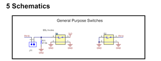
I am not sure why it is happening. I could see following differences in switch schematic of S1 and S2, there is no bias in S2. So my query is if we can use S1 and S2 interchangeably or not. Or under what situation S1/S2 switches are supposed to be used.