This thread has been locked.

If you have a related question, please click the "Ask a related question" button in the top right corner. The newly created question will be automatically linked to this question.

MCU-PLUS-SDK-AM243X: Flash memory

Part Number: MCU-PLUS-SDK-AM243X
Other Parts Discussed in Thread: SYSCONFIG, AM2434

Tool/software:

Hi team,

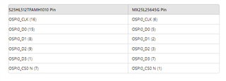
    We uses AM243x_lp to build a custom flash ic board integrating an OSPI-Flash from Macronix. The flash used is the MX25L25645GM2I-08G.The SDK version I am using is mcu_plus_sdk_am243x_09_00_00_35.

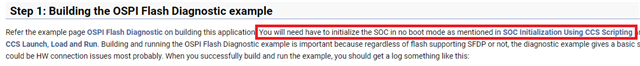
  Referred the following guide for integrating the custom flash - https://software-dl.ti.com/mcu-plus-sdk/esd/AM243X/09_00_00_35/exports/docs/api_guide_am243x/CUSTOM_FLASH_SUPPORT_GUIDE.html#autotoc_md464

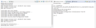
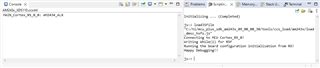
I'm receiving this issue when debugging,

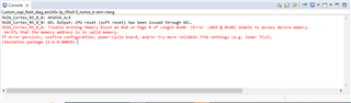
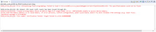
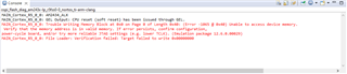
 MAIN_Cortex_R5_0_0: Trouble Writing Memory Block at 0x0 on Page 0 of Length 0x40: (Error -1065 @ 0x40) Unable to access device memory. Verify that the memory address is in valid memory. If error persists, confirm configuration, power-cycle board, and/or try more reliable JTAG settings (e.g. lower TCLK). (Emulation package 12.6.0.00029)
MAIN_Cortex_R5_0_0: File Loader: Verification failed: Target failed to write 0x00000000
MAIN_Cortex_R5_0_0: GEL: File: C:\Users\Abinaya.e\Downloads\Macronix_flash_diag_am243x-lp_r5fss0-0_nortos_ti-arm-clang\Macronix_flash_diag_am243x-lp_r5fss0-0_nortos_ti-arm-clang\Debug\Macronix_flash_diag_am243x-lp_r5fss0-0_nortos_ti-arm-clang.out: Load failed.

Could you kindly advise me on the reason of the problem and how to fix it?

Thanks & regards,

Abinaya E

  • Hello,

    You will need to initialize the SoC first before running the example as mentioned in the guide as well.

    Regards,

    Prashant

  • Hi Prashant,

    Thank you for your response. I checked the no boot mode in https://software-dl.ti.com/mcu-plus-sdk/esd/AM243X/latest/exports/docs/api_guide_am243x/EVM_SETUP_PAGE.html#EVM_SOC_INIT_NOBOOT_MODE.

    I followed the instructions from the above link, but I'm only getting the scripting console and AM243x CIO console. The AM243x ccxml console is not appearing.


    This OSPI FLASH example can run in no boot mode, however it does not support QSPI mode.

    Could you please provide guidance on how to resolve this issue?

    Thanks,

    Abinaya E

  • Hi Abinaya,

    The OSPI_FLASH_DIAG example from am243x-lp folder is coded for AM243x-LP which has QSPI flash. So, you should be able to run this example successfully.

    Could you share logs, if any, in case it did not run successfully?

    Regards,

    Prashant

  • Hi Prashant,

    Thank you for your response.

    We are having trouble integrating a custom flash IC (MX25L25645G) on the AM243x-LP development board.

    Case 1: The OSPI_FLASH_DIAG example works perfectly in QSPI mode on the AM243x-LP development board using the default flash IC. The Commands runs successfully with no boot mode for SoC initialization using CCS scripting, and the flash code works fine in QSPI boot mode.

    Case 2: However, after replacing the default TI flash IC with the custom flash IC (MX25L25645G) and updating the corresponding .json file for the new flash IC, the example no longer works in QSPI mode. The connections between the AM243x and the MX25L25645G are as follows:


    However, when using the custom flash IC in QSPI mode, the example does not work. Specifically, the SOC initialization binary is not functioning correctly, and the second command is halted.


    Could you please provide guidance on:

    1. Any additional configurations or modifications required to support the MX25L25645G in QSPI mode.
    2. Any debugging steps or tools that could help diagnose the issue. We followed this link for adding custom flash  https://software-dl.ti.com/mcu-plus-sdk/esd/AM243X/latest/exports/docs/api_guide_am243x/CUSTOM_FLASH_SUPPORT_GUIDE.html.

    Thank you for your support. I look forward to your response.


    Regards,

    Abinaya

  • Hi Prashant,

    Waiting for your response...

    Thanks,

    Abinaya

  • Hello,

    I am not sure of the exact steps are you following so I will just iterate the steps you need to follow for integrating custom flash part.

    • Perform the SoC initialization using CCS scripting.
    • Run the OSPI_FLASH_DIAG example as it is [DO NOT MODIFY] from the SDK. The example is supposed to work for all flash parts without any changes.
    • Obtain the JSON flash configuration data dumped by the OSPI_FLASH_DIAG example.
    • Change the flash configurations in any example you are running with "Load JSON" button in the Flash module of Sysconfig.
    • Build the example and run.

    If you are following these steps and still see any issue, please let me at what step exactly you see the issue and the corresponding failure logs if any.

    Regards,

    Prashant

  • Hi Prashant,

    Thank you for your response.

    On the AM243x-LP development board, has default flash IC is Infineon's S25HL512TFAMHI010. . The OSPI_FLASH_DIAG example works perfectly in QSPI mode.

    Custom flash issue:

    We are currently facing issues with a custom flash IC MX25L25645G configuration & integrating with AM2434 LP .

    Here's a summary of the steps followed and the response below

    Steps suggested by Prashant :

    • Perform the SoC initialization using CCS scripting. 
      SoC initialization done using CCS scripting in no-boot mode


    • Run the OSPI_FLASH_DIAG example as it is [DO NOT MODIFY] from the SDK. The example is supposed to work for all flash parts without any changes.

      Ran the OSPI_FLASH_DIAG example as it is from the SDK. The example works in QSPI mode on the AM243x-LP. Please find the log in below attachment.

      ospi_diagonstic_example.docx

    • Obtain the JSON flash configuration data dumped by the OSPI_FLASH_DIAG example.
      we obtained the flash information and .json configuration

    • Change the flash configurations in any example you are running with "Load JSON" button in the Flash module of Sysconfig.
      Loaded the obtained .json configuration into the helloworld example sysconfig

    • Build the example and run.
      After debugging we got the following error. So we struct at this point. 

             Could you please help us to identify the cause of this issue .

    Thanks,

    Abinaya 

  • Hello,

    Build the example and run.
    After debugging we got the following error. So we struct at this point. 

    The previous steps looks before this one looks good. At this step, are you resetting the SoC before loading and running the Hello World .out file?

  • Hi Prashant,

    Yes, we are power cycling the SoC in this step before loading and running the Hello World .out file. After that, we received the error.

    The OSPI_FLASH_DIAG example from the SDK debugs correctly for the first time. However, more attempts to run the same default OSPI_FLASH_DIAG example after SOC initialization using CCS scripting result in the following error:

    Could you please help us to identify the cause of this issue.

    Regards,

    Abinaya

  • Hi Prashant,

    We are waiting for your response...

    Thanks,

    Abinaya

  • Hi Abinaya,

    I think you are using the CCXML file from the example itself to launch target configuration and run the example.

    Could you please instead launch configuration using the manually created target configuration file (View -> Target Configurations -> User Defined -> Select the .ccxml file) and then load/run the example by loading the example's .out file?

    You may refer the following guide also

    https://software-dl.ti.com/mcu-plus-sdk/esd/AM243X/latest/exports/docs/api_guide_am243x/HSFS_MIGRATION_GUIDE.html#SBL_BOOT_HS_FS

    Regards,

    Prashant

  • Hi Prashant,

    We followed the link and the steps mentioned in the guide but encountered a debugging error. When we ran the helloworld program, it resulted in a load failed error. 

    Here is what we did:

    1. Created a target configuration file manually (View -> Target Configurations -> User Defined -> Selected the .ccxml file).

    2. Launched the target configuration using the manually created .ccxml file.


    3. Loaded and ran the example by loading the example's .out file.

    Despite following these steps, we encountered a debug load failed error. We have attached the screenshots of the steps we followed

    Could you please help us identify what might be causing this issue?

    Thank you for your assistance.

    Regards,

    Abinaya

  • Hi Prashant,

    We are waiting for your response...

    I wanted to provide another try at the custom flash debugging process I've been working on. I followed the SOC initialization procedures provided in the TI manual Soc Initialization.
    While running the command to flash the SOC initialization binary to the LP, I received an error in which the second command was halted.

    Additionally, I have modified the flash settings in the CCS debugger configurations as follows:

       1. CCS Studio -> Debug Configurations -> Target -> Flash Settings
       2. Enabled the custom flasher.

    It works in UART boot mode and only supports the SOC command executed after debugging.

    Could you kindly advise on any possible solutions or further procedures I should take to solve this issue?

    Thank you for your assistance.

    Regards,

    Abinaya

  • Hi Prashant,

    We are waiting for your response.

    Kindly provide guidance as soon as possible for the custom flash IC.

    Regards,

    Abinaya