This thread has been locked.

If you have a related question, please click the "Ask a related question" button in the top right corner. The newly created question will be automatically linked to this question.

LP-MSPM0L2228: xPSR Register Vaule "10d" = Reserved

Part Number: LP-MSPM0L2228
Other Parts Discussed in Thread: SYSCONFIG, MSPM0G3507, MSPM0L2228, LP-MSPM0G3507

Tool/software:

Hi all,

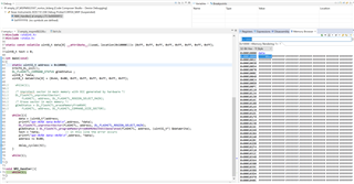
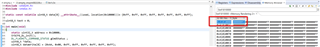
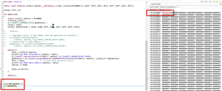
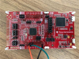
with the LP following unexpected behavior happens.

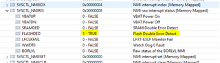
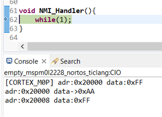
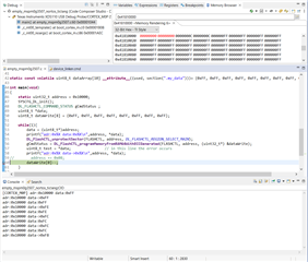
When a write a value to flash memory and read it again, an unexpected interrupt occurs while reading. Whether the interrupt occurs also depends on the value. According to the xPSR register, it should be the exception 10


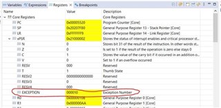
Exception 10 is unfortunately not described in detail in the reference manual and is signed as "RESERVED".

Please can you guide me on that? Thanks in advance

Jens

  • Hi Jens,

    Maybe you can check which interrupt is triggered, NMI or hardfault, or something else.

    You can declare these interrupts in the program and set a while1 loop to see which interrupt the program will stay in.

    B.R.
    Sal

  • Since the display is 6 digits, I'm guessing it's actually binary (6 bits), which would be =2 (NMI).

    [Edit: fixed typo]

  • Hi Jens,

    Yes, Bruce is correct.It seems to be NMI interrupt.

    I suppose you triggered the FLASH ECC error which cuase NMI interrupt. You can double check the register of NMI interrupt source.

    B.R.
    Sal

  • Hi Sal, Hi Bruce,

    Jens is asking this question for me.
    I figured out that you are right. It is the NMI with the reason, flash double error detected, caused by ECC.
    I read out the entire flash, and it looks like there is no ECC generated. I use the command DL_FlashCTL_programMemoryFromRAM64WithECCGenerated to write in to the flash. As I understood the DL documentation right, this command should create the ECC byte automatically. But it doesn't. Do I have to switch on the ECC Generation separately? Anywhere in sysconfig? I couldn't find something.

    If the ECC byte is generated, where will it be located? As the reference manual says flash word size is 64 bits and 72 bits with ECC, I would assume it is directly behind the written data.
    For example
    Data -> 0x100 - 0x107
    ECC -> 0x108
    Is that right?

    Thanks for your support
    Timo

  • Hi Timo,

    Nope, it has separately flash address.

    If you look at datasheet with the memory chapter, you can find below:

    It will have a seperately flash address to store the ECC code.

    B.R.

    Sal

  • Hi Sal,


    because the Flash ECC code has a size of 1kB, it is possible to cover an area in the flash of only 8kB. Right?

    I don't need the ECC, but I get in trouble with that. It is possible to deactivate the ECC, globally?

    I knew I can read out the Flash with an offset of 0x0040.0000. But I like to read from the flash with the original address without this offset.
    I would assume that it could be deactivated, but I don't know how. Can you help me out?

  • How can I decide with part of the flash should be covered by the ECC? Maybe this is the solution for me. I have an individual linker file, but nothing declared for ECC.
    On the other hand, I got this problem over the hole flash. So it seems that the flash is generally covered, but not everywhere could ECC be used.

  • Hi Timo,

    because the Flash ECC code has a size of 1kB, it is possible to cover an area in the flash of only 8kB. Right?

    Yes, this is what I am also confused when I look the table. I think this might be typo or there is something with new feature that I am not aware of.

    If you look at our MSPM0G device, it shows the reasonable region below:

    If I get any progress on this topic, I could update here. But I think this is not the key things you are concerning.

    I don't need the ECC, but I get in trouble with that. It is possible to deactivate the ECC, globally?

    Unfortunately, this is deafult enabled and can not be disabled for safety reason.

    I knew I can read out the Flash with an offset of 0x0040.0000.

    This is correct. 

    Another method is use flash API functions with ecc_generated, the api function could help user to auto set the correct ECC bit with the data.

    B.R.

    Sal

  • Hi Sal,

    if I look at the table for the MSP0G device, I would guess that it is not a separate memory area, more an offset to read the ECC value for this flash area. Which again raises the question, where is the ECC value is stored.

    I already use the ECC command DL_FlashCTL_programMemoryFromRAM64WithECCGenerated. I assumed that this will organize everything necessary in the background. But anyway, I get in this problem. I also tried the versions without ECC but without improvement.

    The API description says that ECC generating should not be disabled. And you said it is not possible to deactivate. Nevertheless, is there something I can check if it is right configured? By the way, there are some typos in the description and the library also.

    Last question, I understood it that way, if I use the API function with ECC than everything should work as expected and no Problem should appear. But what could my problem be? Writing is fine, the value could be read by debugger. Only when I read the value in the flash, the DED Interrupt rises. And it depends on the value I wrote. For example, 0x55 is fine and 0xAA rises the Error. Is there a Problem with the MSPM0L devices? I tried two parts.

    Many thanks

  • Hi Timo,

    where is the ECC value is stored.

    I haven't tested it in M0Lx22x device yet. So it might take me sometime to understand if there is any new feature with the device, due to it has dual flash bank which might cause the deference.

    I already use the ECC command DL_FlashCTL_programMemoryFromRAM64WithECCGenerated.

    Yes, this should be no issue with this. I could try it next week with the device, it also confused me. By the way, could you share your code here for my reference.

    The API description says that ECC generating should not be disabled.

    Yes, and in fact, there is no interface for user to disable this. At least in MSPM0G device not. And I think these two device the flash IP is the same, or there should give some descriptions in the TRM. 

    By the way, there are some typos in the description and the library also.

    Hope this won't confuse you. I definitely agree that the typo should be fixed in future released version.

    For example, 0x55 is fine and 0xAA rises the Error.

    It looks like the you does NOT correctly load the ECC. 

    As I know, the ECC can only detect double bit error, and if you input the error bit more than two, then it could detect and could NOT detect. So it is reasonable, the variable you write is four-bit difference with 0xFF. You can try one-bit difference, such like 0xFE, 0xFD, and check whether FLASHSED always occurs.

    B.R.

    Sal

  • Hi Sal,

    this is my test code, with which I get the error. Address 0x108 is erased by linker and does not contain program code. Other addresses shows also the error, but not all.  Only the first byte of dataWrite is interesting.

    And you are right, if I have a difference from 1 bit to 0xFF it works. But 0x55 has also a difference of 4 bit and works also. Nevertheless, I agree that my ECC is probably not correctly set, but why?

    int main(void)
    {
        static const uint32_t address = 0x108;
        SYSCFG_DL_init();
        DL_FLASHCTL_COMMAND_STATUS gCmdStatus ;
        uint8_t *data;
        uint8_t dataWrite[8] = {0xAA, 0x00, 0xFF, 0xFF, 0xFF, 0xFF, 0xFF, 0xFF};

        data = (uint8_t*)address;
        printf("adr:0x%X data:0x%X\n",address, *data);
        DL_FlashCTL_unprotectSector(FLASHCTL, address, DL_FLASHCTL_REGION_SELECT_MAIN);
        gCmdStatus = DL_FlashCTL_programMemoryFromRAM64WithECCGenerated(FLASHCTL, address, (uint32_t*) &dataWrite);
        uint8_t test = *data;                // in this line the error occurs
        printf("adr:0x%X data->0x%X\n",address, *data);

        while(1);

    }

    void NMI_Handler(){
        while(1);
    }

  • Ok, I figured out that the Linker file is important. I create a new project to demonstrate my problem. Is it possible to share a hole project?

    But for now, I load up my codes here. Created a new empty example for L2228 and deactivate the Linker File Generation in syscfg.

    I have an array at a specified place in the Flash (data[10]). And in this array I want to write. The error only occurs if I write to a defined array. But not always, address 0x20000 works and at the next address 0x20008 the error occurs at my side. Writing is as expected.

    Is there something wrong with my approach?


    main.c ->

    #include "ti_msp_dl_config.h"
    #include <stdint.h>
    #include <stdio.h>
    
    static const volatile uint8_t data[10] __attribute__((used, section(".my_data")))= {0xFF, 0xFF, 0xFF, 0xFF, 0xFF, 0xFF, 0xFF, 0xFF, 0xFF, 0xFF};
    
    int main(void)
    {
        static uint32_t address = 0x20000;
        SYSCFG_DL_init();
        DL_FLASHCTL_COMMAND_STATUS gCmdStatus ;
        uint8_t *data;
        uint8_t dataWrite[8] = {0xAA, 0x00, 0xFF, 0xFF, 0xFF, 0xFF, 0xFF, 0xFF};
    
        while(1){
            data = (uint8_t*)address;
            printf("adr:0x%X data:0x%X\n",address, *data);
            DL_FlashCTL_unprotectSector(FLASHCTL, address, DL_FLASHCTL_REGION_SELECT_MAIN);
            gCmdStatus = DL_FlashCTL_programMemoryFromRAM64WithECCGenerated(FLASHCTL, address, (uint32_t*) &dataWrite);
            uint8_t test = *data;                // in this line the error occurs
            printf("adr:0x%X data->0x%X\n",address, *data);
            address += 0x08;
        }
    
        while(1);
    }
    
    void NMI_Handler(){
        while(1);
    }


    device_lincer.cmd ->

    -uinterruptVectors
    --stack_size=256
    
    MEMORY
    {
        FLASH           (RX)  : origin = 0x00000000, length = 0x00020000
        DATA	        (RX)  : origin = 0x00020000, length = 0x00020000
        SRAM            (RWX) : origin = 0x20200000, length = 0x00008000
        BCR_CONFIG      (R)   : origin = 0x41C00000, length = 0x000000FF
        BSL_CONFIG      (R)   : origin = 0x41C00100, length = 0x00000080
    }
    
    SECTIONS
    {
        .intvecs:   > 0x00000000
        .text   : palign(8) {} > FLASH
        .const  : palign(8) {} > FLASH
        .cinit  : palign(8) {} > FLASH
        .pinit  : palign(8) {} > FLASH
        .rodata : palign(8) {} > FLASH
        .ARM.exidx    : palign(8) {} > FLASH
        .init_array   : palign(8) {} > FLASH
        .binit        : palign(8) {} > FLASH
        .TI.ramfunc   : load = FLASH, palign(8), run=SRAM, table(BINIT)
    
    	.my_data	: palign(8) {} > DATA fill = 0xFFFFFFFF
    
        .vtable :   > SRAM
        .args   :   > SRAM
        .data   :   > SRAM
        .bss    :   > SRAM
        .sysmem :   > SRAM
        .stack  :   > SRAM (HIGH)
    
        .BCRConfig  : {} > BCR_CONFIG
        .BSLConfig  : {} > BSL_CONFIG
    }

  • Even more information.

    I tried the same code as above with an MSPM0G3507, Slightly modified because of the smaller flash. The array starts at 0x10000. And there I got no errors or unexpected interrupts. I also increased the array to 1000 to test a bigger area. Still works as expected.

    This forces the question of what is wrong with the MSPM0L?

  • Hi Timo,

    Yes, you could pack it into a .zip file and directly upload here.

    I will invest some time tomorrow with MSPM0L2228 LaunchPad for the issue.

    B.R.

    Sal

  • My two test projects:

    MSPM0-FlashTest.zip

    Console output for MSPM0L2228:

    Thanks, Sal.

    I'm very curious if you also got the Interrupt and what you find out.

    I would be happy to hear from you tomorrow

    B.R. Timo

  • Hi Timo,

    Sorry for the delay, it is quite busy today. I hope the issue is not that urgent for your application.

    I am planning to do some analysis and update the progress by the end of this week. Thanks for your patience.

    Please also let me know if there any information you want to update.

    B.R.

    Sal

  • Hi Sal,

    to be honest, it is a little bit urgent. We like to use the chip in a new Project and if there should be a bug in the Device that would be a big problem for us. I hope not. Hopefully I did something wrong and you can give me a quick solution. That would be better.

  • Hi Timo,

    I quickly take a test with the file you shared previously.

    It turns out that below code will cause abnormal things occur:

    I comment on the line37. And it could work with no issue.

    Although you assign 0xFF to the address 0x20000, it will also change the ECC code with the value 0xFF. So, you can not program the address without erase operation. To verify it, I also try below code:

    It works without any issue.

    Although I haven't figure out where the ECC code store, but I think you can develop the application code without FLASHDED issue.

    Please let me know if you have any further issue for this.

    So, 

    B.R.

    Sal

  • Hi Sal,

    thanks for your test.

    I thought, if the flash is on 0xFF it is possible to write other values. This also works for writing, the value is in the flash. But the ECC seems to be the problem. I could agree that I have to erase before writing, because of ECC.

    But what makes me really wondering is, that it works without erase on the MSPM0G. The API and TRM seams to be the same.
    Can you explain that?

    The reason why I asking again is that the MSPM0G behave as I would expect. And my algorithm is based on that. So I'm interested in what is the difference between the devices. I know the MSPM0L has two memory banks, but this does not explain the different behavior, for me.

    B.R.
    Timo

  • Hi Timo,

    I don't test your code with G3507, becasue the code seems little different, so please do further analysis on its low level logic.

    Below is the same code which I test in G3507, NMI always trigger.

    This is the expected behavior.

    If you look check the ECC code after the firmware load and not start the FLASH writing, you can find the ECC code has already changed. Below is G3507 data, L2228 should have the same feature.

    After NMI triggered:

    I thought, if the flash is on 0xFF it is possible to write other values.

    Yes, you could. But you ignore the ECC code. It also is a flash region. Which means you you can not write "0" to "1". This makes the error happens.

    I think you should be aware of below:

    Write 0xFF to the FLASH also will change the ECC code. The deafult ECC code is 0xFF which means the corresponding flash is blank, rather than it is 0xFF.

    B.R.

    Sal

  • Hi Sal,

    Thanks for explaining again. I think I get it now.

    On the MSPM0G I can write several times with not getting an interrupt. See my screenshot. There I write, descending from 0xFF at the same address. After a few writes the ECC code is 0. I could run this until 0x00. Without any interrupt. In the Console you can see that the loop runs several times.
    I'm using an early sample of the LP-MSPM0G3507 and I think on this the ECC function is disabled. Otherwise, I could not explain this. What do you think?

    I was thinking the behavior of the MSPM0G was correct, but obviously not. This is what getting me on the wrong way.
    I will order a new LaunchPad and try it again.

    Thanks for investigating that, it was a little bit difficult :)

    The only open question is, where is the ECC value stored on the MSPM0L? This is what is missing to make it totally clear. If you find out anything, please let me know.

    Many thanks
    Timo

  • Hi Timo,

    What do you think?

    It is possible, can you share the picture of your LP here and I can further help check.

    Actually, the pre-sample LP could not use the latest SDK, it will report some warning when you load the program to the device.

    The only open question is, where is the ECC value stored on the MSPM0L? This is what is missing to make it totally clear. If you find out anything, please let me know.

    Yes, I have already discuss with other team experts, and will update here when there is any progress.

    B.R.

    SAl

  • Hi Sal,

    sure I can

    And yes, I got this warning.
    But I didn't know, that it could have this effect.

    B.R.
    Timo

  • Hi Timo,

    Got it. Please use the RTM samples for further test, I suppose it will be work as expected.

    As for MSPM0L2228 ECC code storage flash region, I think it will not hinder your continued development. Since only the interface is provided for users to view, as for writing it, it is written at the same time as the flash address.

    Anyway, I will update when there is a progress. Thanks for your patience.

    B.R.

    Sal