This thread has been locked.

If you have a related question, please click the "Ask a related question" button in the top right corner. The newly created question will be automatically linked to this question.

AM2632: Sitara AM2632 ADC interface with Allegro current sensor

Part Number: AM2632
Other Parts Discussed in Thread: SYSCONFIG

Tool/software:

Dear TI team,

we are facing an issue interfacing an Allegro ACS773 100A (13.2mV/A) with a Sitare AM2632 pinV8.

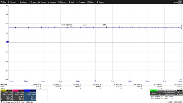
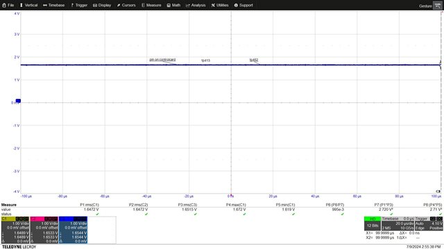
The sensor has a bias of 1.65V (0A = 1.65V).

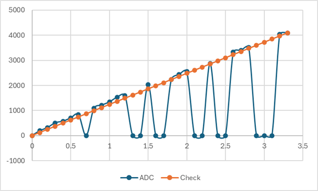
Specifically the Sitara is not able to detect any change of the negative current in the range of 0A - 2A and the positive current is measured as negative with odd values.

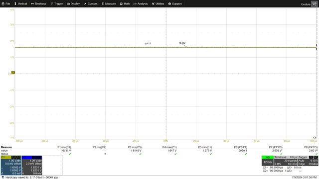
I checked the output of the sensor and it's totally alligned to the expectation, I made a variable current flow into the sensor and its output was always correct.

This is the total sensor circuit

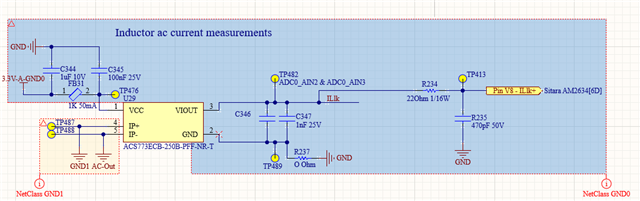
And this is the Sitara's ADC supply

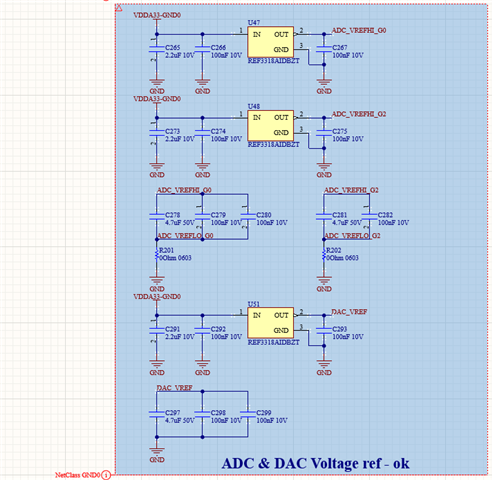
R201 and R202 were removed.

Thanks for your help.

  • Hey Luca,

    Thanks for providing this information so we can help to address your issue. I don't see anything obvious at first glance.

    1) Is it possible to test the analog signals (TP482/TP413) with an AM263x LaunchPad or Control Card?

    2) Can you also provide the ADC/SysConfig configuration code that is being used for testing?

    Best Regards,

    Zackary Fleenor

  • Hello Zackary,

    I can provide you with the SysConfig

  • I just sent you a PM

  • Hello Zackary,

    I can provide you with the SysConfig we are using, for this particular sensor we are using ADC3 IN4 as you can see is the last result from the code snippet. the ADC can read changes as Luca mentioned but there is something odd happening. this is only ADC we are having issues with, as the other ones are working properly

  • Hi, we tried with the controlboard AM263X and we got the same issue, negative current up to -4A (more than 50mV) not seen by the ADC. the ADC drops from 2113 to 2050 applying negative 5.3A (70mV), but 2050 corresponds to 1.652V.

  • Hello Hugo, Luca,

    Thank you for providing this information.

    So your ADC_SoC_NUMBERx variable is actually controlling the which Start of Conversion block (0-15) from the given ADC should be used to read from the results register. 

    From your snippet, it looks like you are trying to grab results from ADC0.[0:2], ADC1.[0:2], ADC2.[0:1], and ADC3.[4]. But you are doing this all from within the ADC0 ISR, I would recommend having a dedicated ISR per ADC that saves the results once the conversion is complete, versus right now, the code is saving the ADC1/2/3 results without any knowledge of the status of those conversions and finalization of result data in the ADCx_RESULT registers. If all ADC are synced to the same trigger and use the same acquisition window, then this may not be as big of an issue.

    What happens if you try:

    gAdc3Results4 = ADC_readResult(CONFIG_ADC3_RESULT_BASE_ADDR, ADC_SOC_NUMBER0)

    Can you please provide the code related to the ADC_setupSoC API call to ensure the correct physical ADC channels/pins are properly configured?

    Best Regards,

    Zackary Fleenor

  • Hello Luca,

    Thanks for checking on this, is it possible to provide scope shots of the following scenarios:

    With Signal Connected to ControlCard ADC Input Pin:

    -Signal directly at VIOUT pin

    -Signal at TP482

    -Signal at TP413

    -Signal at Control Card ADC IN pin

    With Signal Disconnected from the ControlCard ADC Input Pin:

    -Signal directly at VIOUT

    -Signal at TP482

    -Signal at TP413

    Thank you for your time and patience while we continue to debug this issue.

    Best Regards,

    Zackary Fleenor

  • Hello Zackary,

    we are trying to get all of those ADC values from the ISR which  we are triggering all the signals with EPWM10 so it shouldn't be as big of an issue, where can I find ADC_setupSoC?

  • Hi,

    In the following pictures you can see the signal TP482, TP413 and the input pin of the control card

    VIOUT is totally alligned with the rest.

    The first one is with 5A on the sensor, the second with 0A, the signals are completely alligned.

    In the next 2 pictures you will find the TP482 anf TP413 disconnected from the control board


    The behaviours of the signals are coherent with the current sensor specifications.

  • Hey Hugo,

    Understand, I believe this API is called in drivers_open.c.

    Luca was able to provide the SysConfig file and related SW code. I have shared this with our ADC SW expert for additional review.

    Please provide a day or two for proper review and feedback. If you could provide scope/screenshots requested previously in the meantime, it would help to eliminate any possible hardware issues.

    Best Regards,

    Zackary Fleenor

  • Thank you for providing these diagrams. I agree these shots align with what is expected from the sensor specs. The first two screenshots show the charge kickback from sampling the voltage, each little jump should align with a sample trigger. I noticed that they are much more randomly spaced in the 5A signal versus the 0A signal is much more uniform. What is the sampling rate and S+H time being used by ADC3 here?

  • Hi,

    I uploaded the scope screenshoots you requested.

    All the signals you asked for are just totally alligned.

    Regards

    Luca

  • We have ADC3IN4 in a different interrupt now, running at 50kHz and we still see the same behavior, the sample window SYSCLK Counts is at 16

  • Hello Hugo and Luca,

    After further review by SW expert it was noted that the following entries were missing from the end of your .syscfg file:

    adc4.ADC.AIN2.$suggestSolution = "ADC3_AIN2";

    adc4.ADC.AIN4.$suggestSolution = "ADC3_AIN4";

    Screenshot below for reference:

    These lines are necessary for sysconfig to compile the correct pinmux assignment and configuration.

    Can you try with this modification and provide results?

    Best Regards,

    Zackary Fleenor

  • Hi Zackary,

    this is the answer the SW eng gave me:

    I think that's not a problem. those two lines are missing because the pins are locked. if I unlock the pin and rebuild, here is the new syscfg file that HAS the two missing lines.

    Anyway this is the new syscfg

    We are currently using the Pins V8 and T7. V8 is the pin where we cannot read correctly the current, T7 is for an NTC thermal resistor.

    /**
    * These arguments were used when this file was generated. They will be automatically applied on subsequent loads
    * via the GUI or CLI. Run CLI with '--help' for additional information on how to override these arguments.
    * @cliArgs --device "AM263x_beta" --package "ZCZ" --part "AM263x" --context "r5fss0-0" --product "MCU_PLUS_SDK_AM263x@08.06.00"
    * @versions {"tool":"1.17.0+3128"}
    */

    /**
    * Import the modules used in this configuration.
    */
    const adc = scripting.addModule("/drivers/adc/adc", {}, false);
    const adc1 = adc.addInstance();
    const adc2 = adc.addInstance();
    const adc3 = adc.addInstance();
    const adc4 = adc.addInstance();
    const epwm = scripting.addModule("/drivers/epwm/epwm", {}, false);
    const epwm1 = epwm.addInstance();
    const epwm2 = epwm.addInstance();
    const epwm3 = epwm.addInstance();
    const epwm4 = epwm.addInstance();
    const epwm5 = epwm.addInstance();
    const epwm6 = epwm.addInstance();
    const epwm7 = epwm.addInstance();
    const epwm8 = epwm.addInstance();
    const epwm9 = epwm.addInstance();
    const epwm10 = epwm.addInstance();
    const epwm11 = epwm.addInstance();
    const epwm12 = epwm.addInstance();
    const epwm13 = epwm.addInstance();
    const gpio = scripting.addModule("/drivers/gpio/gpio", {}, false);
    const gpio1 = gpio.addInstance();
    const gpio2 = gpio.addInstance();
    const gpio3 = gpio.addInstance();
    const gpio4 = gpio.addInstance();
    const gpio5 = gpio.addInstance();
    const gpio6 = gpio.addInstance();
    const gpio7 = gpio.addInstance();
    const gpio8 = gpio.addInstance();
    const gpio9 = gpio.addInstance();
    const gpio10 = gpio.addInstance();
    const gpio11 = gpio.addInstance();
    const gpio12 = gpio.addInstance();
    const i2c = scripting.addModule("/drivers/i2c/i2c", {}, false);
    const i2c1 = i2c.addInstance();
    const mcan = scripting.addModule("/drivers/mcan/mcan");
    const mcan1 = mcan.addInstance();
    const mcan2 = mcan.addInstance();
    const mcspi = scripting.addModule("/drivers/mcspi/mcspi", {}, false);
    const mcspi1 = mcspi.addInstance();
    const qspi = scripting.addModule("/drivers/qspi/qspi", {}, false);
    const qspi1 = qspi.addInstance();
    const rti = scripting.addModule("/drivers/rti/rti", {}, false);
    const rti1 = rti.addInstance();
    const debug_log = scripting.addModule("/kernel/dpl/debug_log");
    const mpu_armv7 = scripting.addModule("/kernel/dpl/mpu_armv7", {}, false);
    const mpu_armv71 = mpu_armv7.addInstance();
    const mpu_armv72 = mpu_armv7.addInstance();
    const mpu_armv73 = mpu_armv7.addInstance();
    const mpu_armv74 = mpu_armv7.addInstance();
    const gpio_int_xbar = scripting.addModule("/xbar/gpio_int_xbar/gpio_int_xbar", {}, false);
    const gpio_int_xbar1 = gpio_int_xbar.addInstance();
    const gpio_int_xbar2 = gpio_int_xbar.addInstance();
    const int_xbar = scripting.addModule("/xbar/int_xbar/int_xbar", {}, false);
    const int_xbar1 = int_xbar.addInstance();
    const int_xbar2 = int_xbar.addInstance();
    const int_xbar3 = int_xbar.addInstance();
    const int_xbar4 = int_xbar.addInstance();

    /**
    * Write custom configuration values to the imported modules.
    */
    adc1.$name = "CONFIG_ADC0";
    adc1.adcClockPrescaler = "ADC_CLK_DIV_4_0";
    adc1.enableConverter = true;
    adc1.adcSignalMode = "ADC_MODE_DIFFERENTIAL";
    adc1.soc3Channel = "ADC_CH_ADCIN0_ADCIN1";
    adc1.soc4Channel = "ADC_CH_ADCIN0_ADCIN1";
    adc1.soc5Channel = "ADC_CH_ADCIN0_ADCIN1";
    adc1.soc15Channel = "ADC_CH_ADCIN0_ADCIN1";
    adc1.soc14Channel = "ADC_CH_ADCIN0_ADCIN1";
    adc1.soc13Channel = "ADC_CH_ADCIN0_ADCIN1";
    adc1.soc12Channel = "ADC_CH_ADCIN0_ADCIN1";
    adc1.soc11Channel = "ADC_CH_ADCIN0_ADCIN1";
    adc1.soc10Channel = "ADC_CH_ADCIN0_ADCIN1";
    adc1.soc9Channel = "ADC_CH_ADCIN0_ADCIN1";
    adc1.soc8Channel = "ADC_CH_ADCIN0_ADCIN1";
    adc1.soc7Channel = "ADC_CH_ADCIN0_ADCIN1";
    adc1.soc6Channel = "ADC_CH_ADCIN0_ADCIN1";
    adc1.soc0Trigger = "ADC_TRIGGER_EPWM10_SOCA";
    adc1.soc1Trigger = "ADC_TRIGGER_EPWM10_SOCA";
    adc1.soc2Trigger = "ADC_TRIGGER_EPWM10_SOCA";
    adc1.interruptPulseMode = "ADC_PULSE_END_OF_CONV";
    adc1.enableInterrupt1 = true;
    adc1.interrupt1SOCSource = "ADC_SOC_NUMBER2";
    adc1.soc1Channel = "ADC_CH_ADCIN2_ADCIN3";
    adc1.soc2Channel = "ADC_CH_ADCIN4_ADCIN5";
    adc1.enableInterrupt1ContinuousMode = true;
    adc1.soc0Channel = "ADC_CH_ADCIN1_ADCIN0";
    adc1.ADC.$assign = "ADC0";
    adc1.ADC.AIN2.$assign = "ADC0_AIN2";
    adc1.ADC.AIN3.$assign = "ADC0_AIN3";

    adc2.$name = "CONFIG_ADC1";
    adc2.adcSignalMode = "ADC_MODE_DIFFERENTIAL";
    adc2.adcClockPrescaler = "ADC_CLK_DIV_4_0";
    adc2.soc15Channel = "ADC_CH_ADCIN0_ADCIN1";
    adc2.soc14Channel = "ADC_CH_ADCIN0_ADCIN1";
    adc2.soc13Channel = "ADC_CH_ADCIN0_ADCIN1";
    adc2.soc12Channel = "ADC_CH_ADCIN0_ADCIN1";
    adc2.soc11Channel = "ADC_CH_ADCIN0_ADCIN1";
    adc2.soc10Channel = "ADC_CH_ADCIN0_ADCIN1";
    adc2.soc9Channel = "ADC_CH_ADCIN0_ADCIN1";
    adc2.soc8Channel = "ADC_CH_ADCIN0_ADCIN1";
    adc2.soc7Channel = "ADC_CH_ADCIN0_ADCIN1";
    adc2.soc6Channel = "ADC_CH_ADCIN0_ADCIN1";
    adc2.soc5Channel = "ADC_CH_ADCIN0_ADCIN1";
    adc2.soc4Channel = "ADC_CH_ADCIN0_ADCIN1";
    adc2.soc3Channel = "ADC_CH_ADCIN0_ADCIN1";
    adc2.enableConverter = true;
    adc2.soc2Trigger = "ADC_TRIGGER_EPWM10_SOCA";
    adc2.soc1Trigger = "ADC_TRIGGER_EPWM10_SOCA";
    adc2.soc0Trigger = "ADC_TRIGGER_EPWM10_SOCA";
    adc2.soc2Channel = "ADC_CH_ADCIN4_ADCIN5";
    adc2.soc1Channel = "ADC_CH_ADCIN2_ADCIN3";
    adc2.soc0Channel = "ADC_CH_ADCIN0_ADCIN1";
    adc2.ADC.$assign = "ADC1";
    adc2.ADC.AIN0.$assign = "ADC1_AIN0";
    adc2.ADC.AIN1.$assign = "ADC1_AIN1";
    adc2.ADC.AIN2.$assign = "ADC1_AIN2";
    adc2.ADC.AIN3.$assign = "ADC1_AIN3";
    adc2.ADC.AIN4.$assign = "ADC1_AIN4";
    adc2.ADC.AIN5.$assign = "ADC1_AIN5";

    adc3.$name = "CONFIG_ADC2";
    adc3.adcSignalMode = "ADC_MODE_DIFFERENTIAL";
    adc3.soc15Channel = "ADC_CH_ADCIN0_ADCIN1";
    adc3.soc14Channel = "ADC_CH_ADCIN0_ADCIN1";
    adc3.soc13Channel = "ADC_CH_ADCIN0_ADCIN1";
    adc3.soc12Channel = "ADC_CH_ADCIN0_ADCIN1";
    adc3.soc11Channel = "ADC_CH_ADCIN0_ADCIN1";
    adc3.soc10Channel = "ADC_CH_ADCIN0_ADCIN1";
    adc3.soc9Channel = "ADC_CH_ADCIN0_ADCIN1";
    adc3.soc8Channel = "ADC_CH_ADCIN0_ADCIN1";
    adc3.soc7Channel = "ADC_CH_ADCIN0_ADCIN1";
    adc3.soc6Channel = "ADC_CH_ADCIN0_ADCIN1";
    adc3.soc5Channel = "ADC_CH_ADCIN0_ADCIN1";
    adc3.soc4Channel = "ADC_CH_ADCIN0_ADCIN1";
    adc3.soc3Channel = "ADC_CH_ADCIN0_ADCIN1";
    adc3.adcClockPrescaler = "ADC_CLK_DIV_4_0";
    adc3.enableConverter = true;
    adc3.interruptPulseMode = "ADC_PULSE_END_OF_CONV";
    adc3.soc0Trigger = "ADC_TRIGGER_EPWM10_SOCA";
    adc3.interrupt1SOCSource = "ADC_SOC_NUMBER1";
    adc3.soc1Trigger = "ADC_TRIGGER_EPWM10_SOCA";
    adc3.soc1Channel = "ADC_CH_ADCIN2_ADCIN3";
    adc3.soc0Channel = "ADC_CH_ADCIN0_ADCIN1";
    adc3.soc2Channel = "ADC_CH_ADCIN4_ADCIN5";
    adc3.ADC.$assign = "ADC2";
    adc3.ADC.AIN0.$assign = "ADC2_AIN0";
    adc3.ADC.AIN1.$assign = "ADC2_AIN1";
    adc3.ADC.AIN2.$assign = "ADC2_AIN2";
    adc3.ADC.AIN3.$assign = "ADC2_AIN3";

    adc4.$name = "CONFIG_ADC3";
    adc4.enableConverter = true;
    adc4.soc4Channel = "ADC_CH_ADCIN4";
    adc4.soc2Channel = "ADC_CH_ADCIN2";
    adc4.soc2Trigger = "ADC_TRIGGER_EPWM10_SOCA";
    adc4.enableInterrupt1 = true;
    adc4.enableInterrupt1ContinuousMode = true;
    adc4.interrupt1SOCSource = "ADC_SOC_NUMBER4";
    adc4.burstSize = 16;
    adc4.soc4Trigger = "ADC_TRIGGER_EPWM10_SOCA";
    adc4.ADC.$assign = "ADC3";

    epwm1.$name = "CONFIG_EPWM10";
    epwm1.epwmGroup = "EPWM_GROUP3";
    epwm1.epwmTimebase_emulationMode = "EPWM_EMULATION_FREE_RUN";
    epwm1.epwmTimebase_clockDiv = "EPWM_CLOCK_DIVIDER_4";
    epwm1.epwmEventTrigger_EPWM_SOC_A_triggerEnable = true;
    epwm1.epwmEventTrigger_EPWM_SOC_A_triggerSource = "EPWM_SOC_TBCTR_U_CMPA";
    epwm1.epwmEventTrigger_EPWM_SOC_A_triggerEventPrescalar = "1";
    epwm1.epwmTimebase_period = 5000;
    epwm1.epwmCounterCompare_cmpA = 10;
    epwm1.EPWM.$assign = "EPWM10";

    epwm2.$name = "CONFIG_EPWM0";
    epwm2.epwmTimebase_emulationMode = "EPWM_EMULATION_FREE_RUN";
    epwm2.epwmTimebase_counterMode = "EPWM_COUNTER_MODE_UP_DOWN";
    epwm2.epwmTimebase_counterModeAfterSync = "EPWM_COUNT_MODE_UP_AFTER_SYNC";
    epwm2.epwmTimebase_syncOutPulseMode = ["EPWM_SYNC_OUT_PULSE_ON_CNTR_ZERO"];
    epwm2.epwmEventTrigger_enableInterrupt = true;
    epwm2.epwmDeadband_enableRED = true;
    epwm2.epwmDeadband_delayRED = 20;
    epwm2.epwmDeadband_enableFED = true;
    epwm2.epwmDeadband_delayFED = 20;
    epwm2.epwmTimebase_period = 5000;
    epwm2.epwmActionQualifier_EPWM_AQ_OUTPUT_A_shadowMode = true;
    epwm2.epwmActionQualifier_EPWM_AQ_OUTPUT_B_shadowMode = true;
    epwm2.epwmDeadband_inputFED = "EPWM_DB_INPUT_EPWMB";
    epwm2.epwmTimebase_phaseEnable = true;
    epwm2.EPWM.A.$assign = "EPWM0_A";
    epwm2.EPWM.B.$assign = "EPWM0_B";

    epwm3.$name = "CONFIG_EPWM1";
    epwm3.epwmTimebase_emulationMode = "EPWM_EMULATION_FREE_RUN";
    epwm3.epwmTimebase_counterMode = "EPWM_COUNTER_MODE_UP_DOWN";
    epwm3.epwmTimebase_syncInPulseSource = "EPWM_SYNC_IN_PULSE_SRC_SYNCOUT_EPWM0";
    epwm3.epwmTimebase_phaseEnable = true;
    epwm3.epwmTimebase_periodLink = "EPWM_LINK_WITH_EPWM_0";
    epwm3.epwmTimebase_phaseShift = 2;
    epwm3.epwmTimebase_counterModeAfterSync = "EPWM_COUNT_MODE_UP_AFTER_SYNC";
    epwm3.epwmTimebase_period = 5000;
    epwm3.epwmActionQualifier_EPWM_AQ_OUTPUT_A_shadowMode = true;
    epwm3.epwmActionQualifier_EPWM_AQ_OUTPUT_B_shadowMode = true;
    epwm3.epwmDeadband_inputFED = "EPWM_DB_INPUT_EPWMB";
    epwm3.epwmDeadband_enableRED = true;
    epwm3.epwmDeadband_enableFED = true;
    epwm3.epwmDeadband_delayRED = 20;
    epwm3.epwmDeadband_delayFED = 20;
    epwm3.epwmTimebase_periodLoadEvent = "EPWM_SHADOW_LOAD_MODE_SYNC";
    epwm3.EPWM.$assign = "EPWM1";
    epwm3.EPWM.A.$assign = "EPWM1_A";
    epwm3.EPWM.B.$assign = "EPWM1_B";

    epwm4.$name = "CONFIG_EPWM2";
    epwm4.epwmTimebase_counterMode = "EPWM_COUNTER_MODE_UP_DOWN";
    epwm4.epwmTimebase_emulationMode = "EPWM_EMULATION_FREE_RUN";
    epwm4.epwmTimebase_periodLink = "EPWM_LINK_WITH_EPWM_0";
    epwm4.epwmTimebase_phaseEnable = true;
    epwm4.epwmTimebase_counterModeAfterSync = "EPWM_COUNT_MODE_UP_AFTER_SYNC";
    epwm4.epwmTimebase_syncInPulseSource = "EPWM_SYNC_IN_PULSE_SRC_SYNCOUT_EPWM0";
    epwm4.epwmTimebase_phaseShift = 2;
    epwm4.epwmTimebase_period = 5000;
    epwm4.epwmActionQualifier_EPWM_AQ_OUTPUT_A_shadowMode = true;
    epwm4.epwmActionQualifier_EPWM_AQ_OUTPUT_B_shadowMode = true;
    epwm4.epwmDeadband_inputFED = "EPWM_DB_INPUT_EPWMB";
    epwm4.epwmDeadband_enableRED = true;
    epwm4.epwmDeadband_enableFED = true;
    epwm4.epwmDeadband_delayRED = 20;
    epwm4.epwmDeadband_delayFED = 20;
    epwm4.epwmTimebase_periodLoadEvent = "EPWM_SHADOW_LOAD_MODE_SYNC";
    epwm4.EPWM.$assign = "EPWM2";
    epwm4.EPWM.A.$assign = "EPWM2_A";
    epwm4.EPWM.B.$assign = "EPWM2_B";

    epwm5.$name = "CONFIG_EPWM3";
    epwm5.epwmTimebase_emulationMode = "EPWM_EMULATION_FREE_RUN";
    epwm5.epwmTimebase_counterMode = "EPWM_COUNTER_MODE_UP_DOWN";
    epwm5.epwmTimebase_periodLink = "EPWM_LINK_WITH_EPWM_0";
    epwm5.epwmTimebase_phaseEnable = true;
    epwm5.epwmTimebase_syncInPulseSource = "EPWM_SYNC_IN_PULSE_SRC_SYNCOUT_EPWM0";
    epwm5.epwmTimebase_phaseShift = 2;
    epwm5.epwmTimebase_counterModeAfterSync = "EPWM_COUNT_MODE_UP_AFTER_SYNC";
    epwm5.epwmTimebase_period = 5000;
    epwm5.epwmActionQualifier_EPWM_AQ_OUTPUT_A_shadowMode = true;
    epwm5.epwmActionQualifier_EPWM_AQ_OUTPUT_B_shadowMode = true;
    epwm5.epwmDeadband_inputFED = "EPWM_DB_INPUT_EPWMB";
    epwm5.epwmDeadband_enableRED = true;
    epwm5.epwmDeadband_enableFED = true;
    epwm5.epwmDeadband_delayRED = 20;
    epwm5.epwmDeadband_delayFED = 20;
    epwm5.epwmTimebase_periodLoadEvent = "EPWM_SHADOW_LOAD_MODE_SYNC";
    epwm5.EPWM.$assign = "EPWM3";
    epwm5.EPWM.A.$assign = "EPWM3_A";
    epwm5.EPWM.B.$assign = "EPWM3_B";

    epwm6.$name = "CONFIG_EPWM4";
    epwm6.epwmTimebase_emulationMode = "EPWM_EMULATION_FREE_RUN";
    epwm6.epwmTimebase_counterMode = "EPWM_COUNTER_MODE_UP_DOWN";
    epwm6.epwmTimebase_periodLink = "EPWM_LINK_WITH_EPWM_0";
    epwm6.epwmTimebase_phaseEnable = true;
    epwm6.epwmTimebase_counterModeAfterSync = "EPWM_COUNT_MODE_UP_AFTER_SYNC";
    epwm6.epwmTimebase_syncInPulseSource = "EPWM_SYNC_IN_PULSE_SRC_SYNCOUT_EPWM0";
    epwm6.epwmTimebase_phaseShift = 2;
    epwm6.epwmTimebase_period = 5000;
    epwm6.epwmActionQualifier_EPWM_AQ_OUTPUT_A_shadowMode = true;
    epwm6.epwmActionQualifier_EPWM_AQ_OUTPUT_B_shadowMode = true;
    epwm6.epwmDeadband_enableFED = true;
    epwm6.epwmDeadband_enableRED = true;
    epwm6.epwmDeadband_delayRED = 20;
    epwm6.epwmDeadband_delayFED = 20;
    epwm6.epwmDeadband_inputFED = "EPWM_DB_INPUT_EPWMB";
    epwm6.epwmTimebase_periodLoadEvent = "EPWM_SHADOW_LOAD_MODE_SYNC";
    epwm6.EPWM.$assign = "EPWM4";
    epwm6.EPWM.A.$assign = "EPWM4_A";
    epwm6.EPWM.B.$assign = "EPWM4_B";

    epwm7.$name = "CONFIG_EPWM5";
    epwm7.epwmTimebase_emulationMode = "EPWM_EMULATION_FREE_RUN";
    epwm7.epwmTimebase_counterMode = "EPWM_COUNTER_MODE_UP_DOWN";
    epwm7.epwmTimebase_periodLink = "EPWM_LINK_WITH_EPWM_0";
    epwm7.epwmTimebase_phaseEnable = true;
    epwm7.epwmTimebase_syncInPulseSource = "EPWM_SYNC_IN_PULSE_SRC_SYNCOUT_EPWM0";
    epwm7.epwmTimebase_phaseShift = 2;
    epwm7.epwmTimebase_counterModeAfterSync = "EPWM_COUNT_MODE_UP_AFTER_SYNC";
    epwm7.epwmTimebase_period = 5000;
    epwm7.epwmActionQualifier_EPWM_AQ_OUTPUT_A_shadowMode = true;
    epwm7.epwmActionQualifier_EPWM_AQ_OUTPUT_B_shadowMode = true;
    epwm7.epwmDeadband_inputFED = "EPWM_DB_INPUT_EPWMB";
    epwm7.epwmDeadband_enableRED = true;
    epwm7.epwmDeadband_enableFED = true;
    epwm7.epwmDeadband_delayRED = 20;
    epwm7.epwmDeadband_delayFED = 20;
    epwm7.epwmTimebase_periodLoadEvent = "EPWM_SHADOW_LOAD_MODE_SYNC";
    epwm7.EPWM.A.$assign = "EPWM5_A";
    epwm7.EPWM.B.$assign = "EPWM5_B";

    epwm8.$name = "CONFIG_EPWM6";
    epwm8.epwmTimebase_emulationMode = "EPWM_EMULATION_FREE_RUN";
    epwm8.epwmTimebase_counterMode = "EPWM_COUNTER_MODE_UP_DOWN";
    epwm8.epwmTimebase_periodLink = "EPWM_LINK_WITH_EPWM_0";
    epwm8.epwmTimebase_phaseEnable = true;
    epwm8.epwmTimebase_syncInPulseSource = "EPWM_SYNC_IN_PULSE_SRC_SYNCOUT_EPWM0";
    epwm8.epwmTimebase_phaseShift = 2;
    epwm8.epwmTimebase_counterModeAfterSync = "EPWM_COUNT_MODE_UP_AFTER_SYNC";
    epwm8.epwmTimebase_period = 5000;
    epwm8.epwmActionQualifier_EPWM_AQ_OUTPUT_A_shadowMode = true;
    epwm8.epwmActionQualifier_EPWM_AQ_OUTPUT_B_shadowMode = true;
    epwm8.epwmDeadband_inputFED = "EPWM_DB_INPUT_EPWMB";
    epwm8.epwmDeadband_enableFED = true;
    epwm8.epwmDeadband_enableRED = true;
    epwm8.epwmDeadband_delayRED = 20;
    epwm8.epwmDeadband_delayFED = 20;
    epwm8.epwmTimebase_periodLoadEvent = "EPWM_SHADOW_LOAD_MODE_SYNC";
    epwm8.EPWM.A.$assign = "EPWM6_A";
    epwm8.EPWM.B.$assign = "EPWM6_B";

    epwm9.$name = "CONFIG_EPWM7";
    epwm9.epwmTimebase_emulationMode = "EPWM_EMULATION_FREE_RUN";
    epwm9.epwmTimebase_counterMode = "EPWM_COUNTER_MODE_UP_DOWN";
    epwm9.epwmTimebase_periodLink = "EPWM_LINK_WITH_EPWM_0";
    epwm9.epwmTimebase_syncInPulseSource = "EPWM_SYNC_IN_PULSE_SRC_SYNCOUT_EPWM0";
    epwm9.epwmTimebase_phaseEnable = true;
    epwm9.epwmTimebase_phaseShift = 2;
    epwm9.epwmActionQualifier_EPWM_AQ_OUTPUT_A_shadowMode = true;
    epwm9.epwmActionQualifier_EPWM_AQ_OUTPUT_B_shadowMode = true;
    epwm9.epwmDeadband_inputFED = "EPWM_DB_INPUT_EPWMB";
    epwm9.epwmTimebase_periodLoadEvent = "EPWM_SHADOW_LOAD_MODE_SYNC";
    epwm9.epwmTimebase_period = 5000;
    epwm9.epwmDeadband_enableRED = true;
    epwm9.epwmDeadband_enableFED = true;
    epwm9.epwmDeadband_delayRED = 20;
    epwm9.epwmDeadband_delayFED = 20;
    epwm9.EPWM.$assign = "EPWM7";
    epwm9.EPWM.A.$assign = "EPWM7_A";
    epwm9.EPWM.B.$assign = "EPWM7_B";

    epwm10.$name = "CONFIG_EPWM8";
    epwm10.epwmTimebase_emulationMode = "EPWM_EMULATION_FREE_RUN";
    epwm10.epwmTimebase_counterMode = "EPWM_COUNTER_MODE_UP_DOWN";
    epwm10.epwmTimebase_syncInPulseSource = "EPWM_SYNC_IN_PULSE_SRC_SYNCOUT_EPWM0";
    epwm10.epwmTimebase_phaseEnable = true;
    epwm10.epwmTimebase_phaseShift = 2;
    epwm10.epwmActionQualifier_EPWM_AQ_OUTPUT_A_shadowMode = true;
    epwm10.epwmActionQualifier_EPWM_AQ_OUTPUT_B_shadowMode = true;
    epwm10.epwmDeadband_inputFED = "EPWM_DB_INPUT_EPWMB";
    epwm10.epwmDeadband_enableRED = true;
    epwm10.epwmDeadband_enableFED = true;
    epwm10.epwmDeadband_delayRED = 20;
    epwm10.epwmDeadband_delayFED = 20;
    epwm10.epwmTimebase_periodLoadEvent = "EPWM_SHADOW_LOAD_MODE_SYNC";
    epwm10.epwmTimebase_period = 5000;
    epwm10.epwmTimebase_periodLink = "EPWM_LINK_WITH_EPWM_0";
    epwm10.EPWM.$assign = "EPWM8";
    epwm10.EPWM.A.$assign = "EPWM8_A";
    epwm10.EPWM.B.$assign = "EPWM8_B";

    epwm11.$name = "ZeroCrossing";
    epwm11.epwmGroup = "EPWM_GROUP1";
    epwm11.epwmCounterCompare_cmpA = 10;
    epwm11.epwmEventTrigger_EPWM_SOC_A_triggerEnable = true;
    epwm11.epwmEventTrigger_EPWM_SOC_A_triggerSource = "EPWM_SOC_TBCTR_U_CMPA";
    epwm11.epwmEventTrigger_EPWM_SOC_A_triggerEventPrescalar = "1";
    epwm11.epwmTimebase_period = 1000;

    epwm12.$name = "CONFIG_EPWM15";
    epwm12.epwmTimebase_period = 5000;
    epwm12.epwmTimebase_counterMode = "EPWM_COUNTER_MODE_UP_DOWN";
    epwm12.epwmTimebase_counterModeAfterSync = "EPWM_COUNT_MODE_UP_AFTER_SYNC";
    epwm12.epwmTimebase_emulationMode = "EPWM_EMULATION_FREE_RUN";
    epwm12.epwmEventTrigger_enableInterrupt = true;
    epwm12.epwmEventTrigger_interruptSource = "EPWM_INT_TBCTR_D_CMPA";
    epwm12.epwmTimebase_syncInPulseSource = "EPWM_SYNC_IN_PULSE_SRC_SYNCOUT_EPWM0";
    epwm12.epwmCounterCompare_cmpA = 2500;
    epwm12.epwmEventTrigger_interruptEventCount = "1";
    epwm12.epwmCounterCompare_cmpB = 2500;
    epwm12.EPWM.A.$assign = "EPWM15_A";

    epwm13.$name = "CONFIG_EPWM14";
    epwm13.epwmTimebase_syncInPulseSource = "EPWM_SYNC_IN_PULSE_SRC_SYNCOUT_EPWM0";
    epwm13.epwmTimebase_period = 5000;
    epwm13.epwmTimebase_counterMode = "EPWM_COUNTER_MODE_UP_DOWN";
    epwm13.epwmTimebase_counterModeAfterSync = "EPWM_COUNT_MODE_UP_AFTER_SYNC";
    epwm13.epwmEventTrigger_enableInterrupt = true;
    epwm13.epwmEventTrigger_interruptSource = "EPWM_INT_TBCTR_U_CMPA";
    epwm13.epwmEventTrigger_interruptEventCount = "1";
    epwm13.epwmTimebase_emulationMode = "EPWM_EMULATION_FREE_RUN";
    epwm13.epwmCounterCompare_cmpA = 2500;
    epwm13.EPWM.A.$assign = "EPWM14_A";

    gpio1.$name = "GPIO_Illk_polarity";
    gpio1.trigType = "BOTH_EDGE";
    gpio1.GPIO.gpioPin.$assign = "EPWM11_B";

    gpio2.$name = "GPIO_CANSTB_K18";
    gpio2.pinDir = "OUTPUT";
    gpio2.GPIO.gpioPin.$assign = "PR0_PRU0_GPIO1";

    gpio3.$name = "GPIO_CAN2STB_K17";
    gpio3.pinDir = "OUTPUT";
    gpio3.GPIO.gpioPin.$assignAllowConflicts = "PR0_PRU0_GPIO0";

    gpio4.$name = "MUX_A";
    gpio4.pinDir = "OUTPUT";
    gpio4.GPIO.gpioPin.$assign = "EQEP0_STROBE";

    gpio5.$name = "MUX_B";
    gpio5.pinDir = "OUTPUT";
    gpio5.GPIO.gpioPin.$assign = "SDFM0_D2";

    gpio6.$name = "MUX_C";
    gpio6.pinDir = "OUTPUT";
    gpio6.GPIO.gpioPin.$assign = "SPI0_CS0";

    gpio7.pinDir = "OUTPUT";
    gpio7.$name = "DEBUG_GPIO_B14";
    gpio7.GPIO.gpioPin.slewRate = "high";
    gpio7.GPIO.gpioPin.$assign = "EQEP0_A";

    gpio8.$name = "DEBUG_GPIO_A13";
    gpio8.pinDir = "OUTPUT";
    gpio8.GPIO.gpioPin.pu_pd = "pu";
    gpio8.GPIO.gpioPin.$assign = "I2C0_SCL";

    gpio9.$name = "DEBUG_GPIO_L17";
    gpio9.pinDir = "OUTPUT";
    gpio9.GPIO.gpioPin.pu_pd = "pu";
    gpio9.GPIO.gpioPin.$assign = "PR0_MDIO_MDIO";

    gpio10.$name = "DEBUG_GPIO_L18";
    gpio10.pinDir = "OUTPUT";
    gpio10.GPIO.gpioPin.pu_pd = "pu";
    gpio10.GPIO.gpioPin.$assign = "PR0_MDIO_MDC";

    gpio11.$name = "Negative_Current";
    gpio11.trigType = "RISE_EDGE";
    gpio11.GPIO.$assign = "GPIO0";
    gpio11.GPIO.gpioPin.$assign = "RGMII1_RD1";

    gpio12.$name = "Positive_Current";
    gpio12.trigType = "RISE_EDGE";
    gpio12.GPIO.$assign = "GPIO0";
    gpio12.GPIO.gpioPin.$assign = "RGMII1_RXC";

    i2c1.$name = "CONFIG_I2C0";
    i2c1.I2C.SCL.$assign = "UART0_RTSn";
    i2c1.I2C.SDA.$assign = "UART0_CTSn";

    mcan1.$name = "MCAN0_CONFIG";
    mcan1.MCAN.$assign = "MCAN0";

    mcan2.$name = "MCAN1_CONFIG";
    mcan2.MCAN.$assign = "MCAN1";

    mcspi1.$name = "External_eeprom";
    mcspi1.SPI.CLK.$assign = "SPI1_CLK";
    mcspi1.SPI.D0.$assign = "SPI1_D0";
    mcspi1.SPI.D1.$assign = "SPI1_D1";
    mcspi1.mcspiChannel[0].$name = "CONFIG_MCSPI_CH0";
    mcspi1.mcspiChannel[0].CSn.$assign = "SPI1_CS0";

    qspi1.$name = "CONFIG_QSPI0";
    qspi1.advanced = true;
    qspi1.QSPI.QSPI_D2.pu_pd = "pu";
    qspi1.QSPI.QSPI_D3.pu_pd = "pu";

    const edma = scripting.addModule("/drivers/edma/edma", {}, false);
    const edma1 = edma.addInstance({}, false);
    edma1.$name = "CONFIG_EDMA0";
    qspi1.edmaConfig = edma1;
    mcspi1.edmaDriver = edma1;
    edma1.edmaRmDmaCh[0].$name = "CONFIG_EDMA_RM0";
    edma1.edmaRmQdmaCh[0].$name = "CONFIG_EDMA_RM1";
    edma1.edmaRmTcc[0].$name = "CONFIG_EDMA_RM2";
    edma1.edmaRmParam[0].$name = "CONFIG_EDMA_RM3";

    rti1.$name = "CONFIG_RTI0";
    rti1.counter0Enable = true;
    rti1.compare0Enable = true;
    rti1.cntr0OpFreq = 100000;
    rti1.eventCallback0 = "DAQ_One";
    rti1.enableIntr0 = true;
    rti1.continueOnSuspend = true;
    rti1.usecPerTick0 = 100;

    debug_log.enableUartLog = true;
    debug_log.uartLog.$name = "CONFIG_UART0";
    debug_log.uartLog.UART.RXD.$assign = "UART0_RXD";
    debug_log.uartLog.UART.TXD.$assign = "UART0_TXD";

    mpu_armv71.$name = "CONFIG_MPU_REGION0";
    mpu_armv71.size = 31;
    mpu_armv71.attributes = "Device";
    mpu_armv71.accessPermissions = "Supervisor RD+WR, User RD";
    mpu_armv71.allowExecute = false;

    mpu_armv72.$name = "CONFIG_MPU_REGION1";
    mpu_armv72.size = 15;
    mpu_armv72.accessPermissions = "Supervisor RD+WR, User RD";

    mpu_armv73.$name = "CONFIG_MPU_REGION2";
    mpu_armv73.baseAddr = 0x80000;
    mpu_armv73.size = 15;
    mpu_armv73.accessPermissions = "Supervisor RD+WR, User RD";

    mpu_armv74.$name = "CONFIG_MPU_REGION3";
    mpu_armv74.accessPermissions = "Supervisor RD+WR, User RD";
    mpu_armv74.baseAddr = 0x70000000;
    mpu_armv74.size = 21;

    gpio_int_xbar1.$name = "CONFIG_GPIO_INT_XBAR0";
    gpio_int_xbar1.instance = "GPIO_INT_XBAR_VIM_MODULE0_0";
    gpio_int_xbar1.xbarOutput = "GPIO_INT_XBAR_GPIO_MUX_29";

    gpio_int_xbar2.$name = "CONFIG_GPIO_INT_XBAR1";
    gpio_int_xbar2.xbarOutput = "GPIO_INT_XBAR_GPIO_MUX_32";
    gpio_int_xbar2.instance = "GPIO_INT_XBAR_VIM_MODULE0_1";

    int_xbar1.$name = "CONFIG_INT_XBAR0";
    int_xbar1.xbarOutput = ["ADC0_INT1"];

    int_xbar2.$name = "CONFIG_INT_XBAR1";
    int_xbar2.xbarOutput = ["ADC3_INT1"];
    int_xbar2.instance = "INT_XBAR_1";

    int_xbar3.$name = "CONFIG_INT_XBAR2";
    int_xbar3.instance = "INT_XBAR_2";
    int_xbar3.xbarOutput = ["EPWM14_INT"];

    int_xbar4.$name = "CONFIG_INT_XBAR3";
    int_xbar4.instance = "INT_XBAR_3";
    int_xbar4.xbarOutput = ["EPWM15_INT"];

    /**
    * Pinmux solution for unlocked pins/peripherals. This ensures that minor changes to the automatic solver in a future
    * version of the tool will not impact the pinmux you originally saw. These lines can be completely deleted in order to
    * re-solve from scratch.
    */
    adc1.ADC.AIN0.$suggestSolution = "ADC0_AIN0";
    adc1.ADC.AIN1.$suggestSolution = "ADC0_AIN1";
    adc1.ADC.AIN4.$suggestSolution = "ADC0_AIN4";
    adc1.ADC.AIN5.$suggestSolution = "ADC0_AIN5";
    adc3.ADC.AIN4.$suggestSolution = "ADC2_AIN4";
    adc3.ADC.AIN5.$suggestSolution = "ADC2_AIN5";
    adc4.ADC.AIN0.$suggestSolution = "ADC3_AIN0";
    adc4.ADC.AIN1.$suggestSolution = "ADC3_AIN1";
    adc4.ADC.AIN2.$suggestSolution = "ADC3_AIN2";
    adc4.ADC.AIN3.$suggestSolution = "ADC3_AIN3";
    adc4.ADC.AIN4.$suggestSolution = "ADC3_AIN4";
    adc4.ADC.AIN5.$suggestSolution = "ADC3_AIN5";
    epwm1.EPWM.A.$suggestSolution = "EPWM10_A";
    epwm1.EPWM.B.$suggestSolution = "EPWM10_B";
    epwm2.EPWM.$suggestSolution = "EPWM0";
    epwm7.EPWM.$suggestSolution = "EPWM5";
    epwm8.EPWM.$suggestSolution = "EPWM6";
    epwm11.EPWM.$suggestSolution = "EPWM9";
    epwm11.EPWM.A.$suggestSolution = "EPWM9_A";
    epwm11.EPWM.B.$suggestSolution = "EPWM9_B";
    epwm12.EPWM.$suggestSolution = "EPWM15";
    epwm12.EPWM.B.$suggestSolution = "EPWM15_B";
    epwm13.EPWM.$suggestSolution = "EPWM14";
    epwm13.EPWM.B.$suggestSolution = "EPWM14_B";
    gpio1.GPIO.$suggestSolution = "GPIO0";
    gpio2.GPIO.$suggestSolution = "GPIO0";
    gpio3.GPIO.$suggestSolution = "GPIO0";
    gpio4.GPIO.$suggestSolution = "GPIO0";
    gpio5.GPIO.$suggestSolution = "GPIO0";
    gpio6.GPIO.$suggestSolution = "GPIO0";
    gpio7.GPIO.$suggestSolution = "GPIO0";
    gpio8.GPIO.$suggestSolution = "GPIO0";
    gpio9.GPIO.$suggestSolution = "GPIO0";
    gpio10.GPIO.$suggestSolution = "GPIO0";
    i2c1.I2C.$suggestSolution = "I2C2";
    mcan1.MCAN.RX.$suggestSolution = "MCAN0_RX";
    mcan1.MCAN.TX.$suggestSolution = "MCAN0_TX";
    mcan2.MCAN.RX.$suggestSolution = "MCAN1_RX";
    mcan2.MCAN.TX.$suggestSolution = "MCAN1_TX";
    mcspi1.SPI.$suggestSolution = "SPI1";
    qspi1.QSPI.$suggestSolution = "QSPI";
    qspi1.QSPI.QSPI_D0.$suggestSolution = "QSPI_D0";
    qspi1.QSPI.QSPI_D1.$suggestSolution = "QSPI_D1";
    qspi1.QSPI.QSPI_D2.$suggestSolution = "QSPI_D2";
    qspi1.QSPI.QSPI_D3.$suggestSolution = "QSPI_D3";
    qspi1.QSPI.QSPI_CLK.$suggestSolution = "QSPI_CLK";
    qspi1.QSPI.QSPI_CSn0.$suggestSolution = "QSPI_CSn0";
    rti1.RTI.$suggestSolution = "RTI1";
    debug_log.uartLog.UART.$suggestSolution = "UART0";

  • We tried the code with the additional lines on the .syscfg, no changes. We applied up to 70mV on voltage variation and the ADC wasn't able to catch it.

  • Hello Luca,

    Apologies for the delay here. You tested 70mV voltage variation with a Control Card or with the custom hardware?

    Best Regards,

    Zackary Fleenor

  • Hi, in both cases we have erroneous readings.

  • Hello Zackary,

    we tested ADC3IN4 with DC values incrementing with 100mV increments and at some points we got inconsistent readings as you can see in the graph; Orange is the expected value and Blue is the result value from the conversion, we put 0 where the values were not consistent. we ran the same test using ADC3IN5 and we don't see that issue, there was no software modification besides changing what channel we are getting the result from, test was done using the control Card.

  • Thank you for the updates.

    My understanding is that only ADC3_AIN4 is experiencing the issue of inconsistent readings by occasionally returning a 0V value. You are experiencing this phenomenon on both custom hardware and the ControlCard/Launchpad?


    Is anything connected to TP482 and TP413 when the ADC is sampling?

    Best Regards,

    Zackary Fleenor

  • The adc is not returning a 0V value, in those points the reading is inconsistent and very noisy (+- 1000 raw values), I replaced the random readings with 0V because I just wanted to highlight them.

    We are experiencing this with launchpad and our board.

    there is nothing connected to TP482 TP413

  • Hello Luca,

    Can you try using the Launchpad + Signal Generator with ADC3_AIN4 and a slow ramping signal to replicate the sensor signal? I am unable to replicate the issue you are seeing when using this method. Can you also please provide the latest .syscfg and related ADC Code for review by our SW expert?

    Best Regards,

    Zackary Fleenor