This thread has been locked.

If you have a related question, please click the "Ask a related question" button in the top right corner. The newly created question will be automatically linked to this question.

TM4C123BE6PM: How to load the serial flash loader or properly configured bootloader to program TM4C123BE6PM?

Part Number: TM4C123BE6PM
Other Parts Discussed in Thread: EK-TM4C123GXL, UNIFLASH

Tool/software:

Dear Team,

I am using TM4C123BE6PM Tiva-C Series microcontroller in my custom designed board.

I am able to load the program using JTAG connector where Now I want utilize the UART of the controller to program the chip.

The board consist of the FTDI FT231 IC.

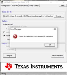
Following is the error I encounter when I tried to perform the programming using LM FLASH Programmer
Kindly Guide me to understand how to load bootloader for serial port based programming and overcome above issue?

Regards,

Aditya Mhatre

Embedded Hardware Design Engineer

  • I am able to load the program using JTAG connector where Now I want utilize the UART of the controller to program the chip.

    The board consist of the FTDI FT231 IC.

    I have some questions and feedback.

     - Which UART are using to use? If you are using the ROM-based serial bootloader then only UART0 can be used. You cannot use other UART instances like UART1, UART2 and etc,

      - Make sure on the LM flash programmer you specify the correct COM port. You can find out what COM port from Windows Device Manager. Also make sure the COM port settings are identical between the PC and the UART in terms of baudrate, stop bits and no parity.

     - If you are not using the ROM-based serial bootloader then I assume you are intending to use the flash-based bootloader. In this case, do you have the flash-based bootloader which is a small piece of program starting at 0x0. Check your flash content to see if you have the flash-based bootloader at 0x0. 

     - If you are not familiar with the flash-based bootloader then there are examples in TivaWare SDK. Refer to C:\ti\TivaWare_C_Series-2.2.0.295\examples\boards\ek-tm4c123gxl\boot_serial and C:\ti\TivaWare_C_Series-2.2.0.295\examples\boards\ek-tm4c123gxl\boot_demo1. Note that boot_serial is a flash-based bootloader that must first be loaded through JTAG and resides at 0x0. Once it is loaded and running, it will load the example application (boot_demo1). After the application is loaded, it will blink a LED.

      - I strongly suggest you first play with the examples on the LaunchPad and get a feel on how it works. If you can successfully run the examples on the LaunchPad then the next thing is run the same example on your custom board before you change to your own application. 

      - I also strongly suggest that you run a simple hello program so that 'Hello' message is successfully printed on the terminal window through the COM port and your  FT231 IC. This is to make sure there  FT231 IC is corrected enumerated for serial transport. 

  • Dear Charles,

    Thanks for the reply.

    1. Which UART are using to use? If you are using the ROM-based serial bootloader then only UART0 can be used. You cannot use other UART instances like UART1, UART2 and etc,

    Answer: I am using UART0 only where as you mentioned ROM based serial bootloader then kindly let me know how to load the ROM based serial bootloader or does the tm4c123be6m already consist of the ROM-based Serial bootloader?

    2. Make sure on the LM flash programmer you specify the correct COM port. You can find out what COM port from Windows Device Manager. Also make sure the COM port settings are identical between the PC and the UART in terms of baud rate, stop bits and no parity.

    Answer: The detected port for the FTDI chip is selected in COM port by understanding from the device manager where Baud rate I am keeping as 115200.

    3.  If you are not using the ROM-based serial bootloader then I assume you are intending to use the flash-based bootloader. In this case, do you have the flash-based bootloader which is a small piece of program starting at 0x0. Check your flash content to see if you have the flash-based bootloader at 0x0. 

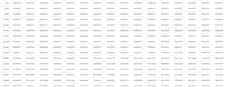
    Answer: Request you to guide me how to understand the which bootloader I have in my IC. Following are the memory map of my chip.

    Below picture shows the memory map after reset and unlock sequence from CMD:


    Below Picture shows the memory map after loading blink LED program:

    4. If you are not familiar with the flash-based bootloader then there are examples in TivaWare SDK. Refer to C:\ti\TivaWare_C_Series-2.2.0.295\examples\boards\ek-tm4c123gxl\boot_serial and C:\ti\TivaWare_C_Series-2.2.0.295\examples\boards\ek-tm4c123gxl\boot_demo1. Note that boot_serial is a flash-based bootloader that must first be loaded through JTAG and resides at 0x0. Once it is loaded and running, it will load the example application (boot_demo1). After the application is loaded, it will blink a LED.

    Answer: Will you Elaborate the procedure for this as this has to be done from uniflash or LM Flash Programmer? 

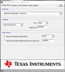
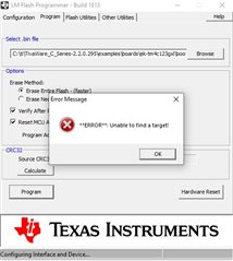
    Where when I tried to load via LM Flash Programmer I am facing "unable to find target: error. Please find below the setting of the LM Flash Programmer

    5.  I strongly suggest you first play with the examples on the LaunchPad and get a feel on how it works. If you can successfully run the examples on the LaunchPad then the next thing is run the same example on your custom board before you change to your own application.

    Answer: We don't have the Launch Pad/Evaluation Board where I would like to mentioned that we where able to perform and load few programs in custom board like blink etc. but via JTAG where now only target is to achieve via serial UART using USB to UART on board FTDI chip.

    6. I also strongly suggest that you run a simple hello program so that 'Hello' message is successfully printed on the terminal window through the COM port and your  FT231 IC. This is to make sure there  FT231 IC is corrected enumerated for serial transport. 

    Answer: I have verified FT231 operation by doing the loop back on the UART Side of FT231.


    Sorry for so many questions but request you to kindly support for the same...

    Regards,

    Aditya R. Mhatre

    Embedded Hardware Design Engineer

  • HI,

    Answer: I am using UART0 only where as you mentioned ROM based serial bootloader then kindly let me know how to load the ROM based serial bootloader or does the tm4c123be6m already consist of the ROM-based Serial bootloader?

    TM4C123 is already preloaded with the bootloader and the peripheral drivers in the ROM. It is your choice whether you want to use the ROM-based bootloader or the flash-based bootloader. 

    Answer: Will you Elaborate the procedure for this as this has to be done from uniflash or LM Flash Programmer? 

    Where when I tried to load via LM Flash Programmer I am facing "unable to find target: error. Please find below the setting of the LM Flash Programmer

    See below instructions to use the flash-based bootloader where you have more flexibility in terms of which UART instance to use. For ROM bootloader, it must be UART0 but for flash-based bootloader, you can use UART0, UART1 and etc but the stock TivaWare flash-based bootloader example uses UART0. It is changeable to other UARTx if you want. I strongly suggest you read the Bootloader user's guide to understand the concept. https://www.ti.com/lit/pdf/spmu301

     1 Load the boot_serial to the flash using CCS or LM flash programmer or Uniflash via JTAG. Loading boot_serial is no different than loading a blinky program.

       2. Run the boot_serial program. 

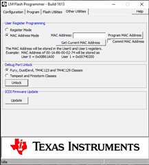
       3. In LM flash programmer change to manual mode to select UART bootloading. Make sure you select the correct COM port. Go to the Windows device manager to find out which COM port is enumerated. Another important thing is to make sure in your Port setting for the COM port in your Windows, it has the matching baudrate which is 115200, no parity and 1 stop bit. Below COM11 is for my machine. Your machine will have a different COM port. 

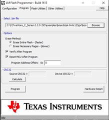
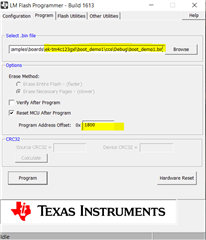
     4 Go the program tab. Provide the path to the boot_demo1.bin file and make sure to enter the correct offset address which is 0x1800. Hit the program button and you will see the transfer starts and finished with the number of bytes transferred in the bottom. 

    5. You can press the reset button on the board.. You should see the LED blinking. The example is for the LaunchPad. If your custom board does not have LED at the specified pin then you will not see LED blinking. Read the boot_demo1.c file which is very simple. You can modify it if you have LED on a different pin.

    6. Press the SW1. The LED should stop blinking as it has jumped to the bootloader. Again, this depends if your custom board has a switch as the example is build for the LaunchPad that has a user switch.

    7. Go to step 4 again and hit the program button to load another program like the boot_demo2 

  • Hello Charles,

    Thank you for giving detailed procedure...

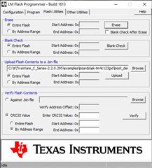
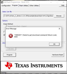
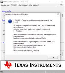
    I tried as you mentioned in steps, where as mentioned in step 4 after hitting the program button I encounter with following error:

    This time "target not found error' was not occurred.

    Kindly let me know about the error and how to overcome it.

    Aditya Ravindra Mhatre

    Embedded Hardware Design Engineer
  • I have some questions.

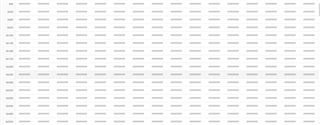
    - Have you loaded the flash bootloader at 0x0? What does memory browser window show for flash memory starting at 0x0? 

    - Can you run the hello example project? Can you see the 'Hello' message sent to the terminal window via the COM port. I know you have run some loopback test on FT231. But that does not guarantee all the send and receive are correct up to your PC side. If you cannot see the 'Hello' message on your terminal window, this will be the first thing to debug.

    - Can you probe the TX and RX pin for UART0? Do you see any signals on these two pins?

    - Can you try a different PC? Do you see the same problem?

    - I strongly you acquire a LaunchPad. It is a low-cost development board for $16.99. You can easily develop and debug your software using the LaunchPad before porting it to your final board. https://www.ti.com/tool/EK-TM4C123GXL