Part Number: TMS570LC4357
Other Parts Discussed in Thread: HALCOGEN
Tool/software:
Dear TI support,
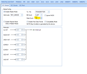
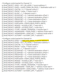
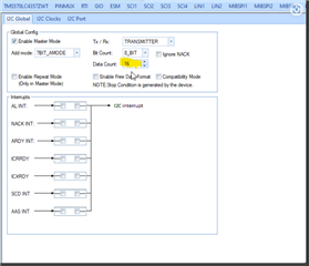
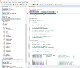
Do you example source code and HalcoGen configuration for I2C read and write by DMA controller?
Part Number: TMS570LC4357
Other Parts Discussed in Thread: HALCOGEN
Tool/software:
Dear TI support,
Do you example source code and HalcoGen configuration for I2C read and write by DMA controller?