This thread has been locked.

If you have a related question, please click the "Ask a related question" button in the top right corner. The newly created question will be automatically linked to this question.

MSPM0G3507: MSPM0G3507

Part Number: MSPM0G3507
Other Parts Discussed in Thread: UNIFLASH,

Tool/software:

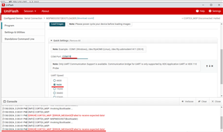
Hi, I am trying to implement the BSL example using USB-TTL UART module as a medium for PC Host as in this thread. I have already loaded "bsl_software_invoke_app_demo_uart" project into the LP-MSPM0G3507 EVK and just powered up the EVK with only 3.3V, GND and NRST from the Host PC's another USB Port.

  1. I pressed S2 switch and I saw the Green LED lit once (before it goes into the BSL invoking.).
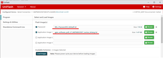
  2. I loaded the .txt image file in the UniFlash app after connected to the (USB-TTL UART module) COM Port.
  3. I clicked load image. 

But it's failed.
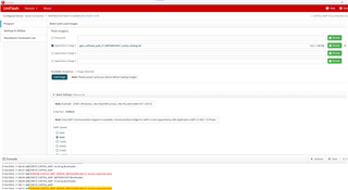
Please help and thanks in advance, experts. 

  • Currently, Uniflash has some problem to support BSL. I would suggest you to use the BSL GUI

  • Hi Eason,

    thanks for the prompt response. Which .exe should I use as there three folders inside GUI_EXE folder in the SDK version I am using.

    And a few more questions. 

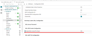
    should I need to modify anything on "bsl_software_invoke_app_demo_uart" project as I don't need "BSL inovke pin" in my application.

  • Hi Eason,

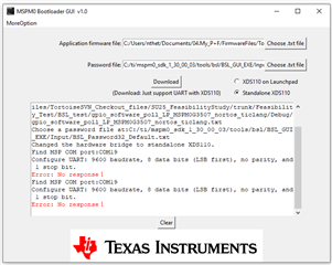
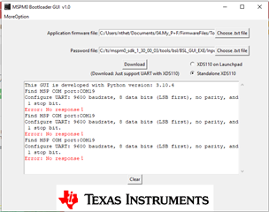
    I found .exe in the old SDK and so I used it to test and I still can't able to load the gpio_software_poll image txt file.

    As I use a USB-TTL UART module, I checked Standalone XDS110. 
    I tried a few different methods. First, I pressed the S2 button on EVK and press Download in the app which also didn't work.
    I have removed BSL Invoke Pin feature in the software "bsl_software_invoke_app_demo_uart" 

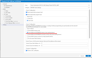
    and checked NON-MAIN to erase as well before I loaded the FW into EVK.

  • The reson why the latest SDK don't provide .exe file is that TI don't have authority to Python complier.

    I think the problem lies on that the standalone XDS110 doesn't point to USB-TTL UART module. See from the error, it shows there is no wanted UART send back data.

    Can you choose "XDS110 on Launchpad" and try with MSPM0G3507 LP. You can also refer to this doc to do the download.https://www.ti.com/lit/pdf/slaae88?keyMatch=mspm0%20bootloader

  • Hi Eason,

    I have tried using using LP EVK and can only able to flash to LP itself.
    I have also tried in the implementation application note.

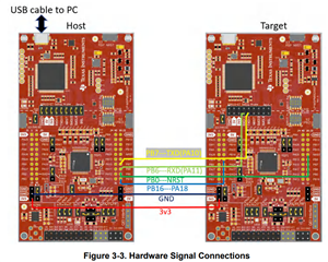
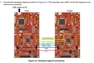
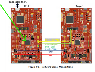
    I connected as mentioned in this example.

    On host MCU (Left LP EVK), I have flashed "bsl_host_mcu_to_mspm0g1x0x_g3x0x_target_uart" FW and on target MCU (right LP EVK), "bsl_software_invoke_app_demo_uart" FW.

    I have tried flashing using "Standalone XDS110" and still there is no response.


    it can only download to HOST MCU if I select XDS110 on Launchpad.

    But this is not my intention. I want to upload to Target MCU. 

    Please kindly help. PrayPray

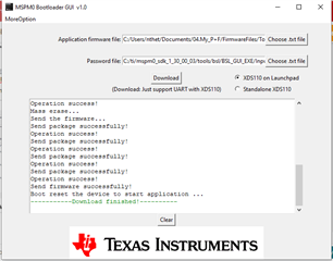
  • The reason why you will success in your second try is that you are using ROM BSL + GUI.  That is what you want.

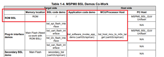
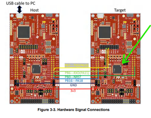
    The hardware setup is for this:

    The key difference is that the host is different.

  • Hi Eason, yes. I did exactly the same as in your second image. I flashed "host_mcu_to_target_uart" FW into the Host EVK and flashed "software_invoke_demo" FW into the target EVK. And try to load "gpio_software_poll.txt" with xefault password file.

    (the only minor change I modified in the software_invoke_demo is that the software will be invoked after Blue LED is blinking 5times instead of waiting for hard-pin invoke or 0x22 data received from UART.)

    I hard-reset the target board first and I saw the Blue LED blinks for 5times and Green LED blinks once and off (meaning the BSL is invoked).

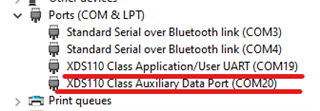
    Then I clicked "Load Images" in the UniFlash app (I have chosen the Correct COM port (COM19) and baud rate as well.)

    But it's still failed. I have even changed to Data Port COM Port (COM20) just incase and it's still failed.


    Apology if I didn't explain you clearly and let me know if you need any more details. Thanks.

  • Can I know what you want to do? I think you want to use PC to program MSPM0 through BSL right? If so, you already succeed. With this setup, you don't need to program any code into MSPM0 ahead. You just need to use the GUI to follow the steps to download your code directly.

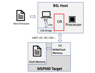
    If you want to use this setup. That means the host is MCU not PC. The code downloading into the traget should be saved into the bsl_host_mcu_to_m0x.

    Please detailed look into this picture. It is "or" not "and". Only use PC, you need a USB bridge. I would suggest you to look into the doc https://www.ti.com/lit/pdf/slaae88?keyMatch=mspm0%20bootloader to have a better understand on bootloader. 

  • Hi Eason, I want to use USB Bridge-PC as a BSL Host and so I used UniFlash but couldn't able to load the image. So I tried to use MCU as a host and tried again and it's still failing.

    I tried this example. (MCU as a host)

    I connected all the wires according to this setup.

    I used UniFlash and tried to load in the FW image (gpio_software_poll.txt) into "Target" board. I can see the "Target" board goes into the BSL invoking.

    Then I click "Load Images" from UniFlash after selecting the "gpio_software_poll.txt" file and "password" file.

    But I received the same error. "Failed to receive expected data" even though I chose the correct COM port.

    What I mean in the earlier post was that the image loaded went into the TI's MCU on the Host side EVK if I selected "XDS on launch pad" in "MSPM0_BSL_GUI.exe"

    But I want to load the image into the Target MCU.

    Apology if I can't explain you well enough. Please let me know if you still don't get my question. Thanks.

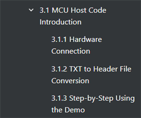
  • If you want to use MCU as the host, please read  these chapters. Can you follow the steps one by one? Uniflash is not needed.

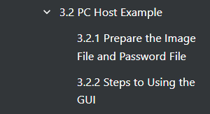
    If you want to use PC as the host, please read. 

  • Hi Eason, thanks for the reply. I checked and found out that I misunderstood the concept and thanks again for pointing out. But I would like to check is there a way to use a normal USB-UART bridge without using XDS110 on the launch pad as in this thread

  • You can do that, first you need to pull PA18 to be high or connect it to VCC. After MCU power up, it will enter BSL mode automatically. Then you can use uniflash to try to download the code through the right COM port.

  • Hi Eason, thanks. But I need to use the software invoke feature. I will try this. Thanks again for your support.