This thread has been locked.

If you have a related question, please click the "Ask a related question" button in the top right corner. The newly created question will be automatically linked to this question.

TM4C1290NCPDT: Trying to get a pulse counter working.

Part Number: TM4C1290NCPDT

Tool/software:

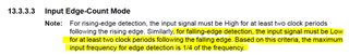
There is a pulse train on port D7 that I'm trying to count.  Code:

SysCtlPeripheralEnable(SYSCTL_PERIPH_GPIOD);

    SysCtlPeripheralEnable(SYSCTL_PERIPH_TIMER4);

    GPIOPinTypeTimer(GPIO_PORTD_BASE, 0x80);

    GPIOPinConfigure(GPIO_PD7_T4CCP1);

    // Lots of code runs here so the peripherals are ready.

    TimerDisable(TIMER4_BASE, TIMER_B);

    TimerConfigure(TIMER4_BASE, TIMER_CFG_SPLIT_PAIR | TIMER_CFG_B_CAP_COUNT_UP | TIMER_CFG_B_ACT_NONE);

    TimerControlEvent(TIMER4_BASE, TIMER_B, TIMER_EVENT_NEG_EDGE);

    TimerEnable(TIMER4_BASE, TIMER_B);

    TIMER4_TBV_R = 0;

    // Every 1/4 second...

    Count = TimerValueGet(TIMER4_BASE, TIMER_B);

    TIMER4_TBV_R = 0;

But Count is always zero.

Thanks, Doug

  •     TIMER4_TBV_R = 0;

        // Every 1/4 second...

        Count = TimerValueGet(TIMER4_BASE, TIMER_B);

        TIMER4_TBV_R = 0;

    Hi Doug,

      You comment seems to suggest that you want to measure the time elapsed from a negative edge to a negative edge. Is that what you want? The reason I ask is because you are configuring the timer with TIMER_CFG_B_CAP_COUNT_UP. This is for counting number of edges, not counting time. If you really meant to count edges then how many edges are you providing within 1/4 second? Please also note regardless of counting time or counting edges, the input must be low for at least two clock periods following the falling edge. Also note that the counter is only 16 bits. This means the counter will roll over to 0 when it overflows. If you are counting time then you need to use TIMER_CFG_B_CAP_TIME_UP.

  • Hi Charles,

    I am counting pulses, not time between pulses.  The pulse width is 10uS and the system clock is 50nS so no problem with needing two clocks to capture.  The typical max 1/4 second count is about 150, so 16 bits is plenty.  FYI, when counting pulses the Pre-Scaler actually becomes a "Post-Scaler", the top 4 bits of the counter, so that it's actually a 24 bit counter.

    Regards, Doug

  • Hi Doug,

      Can you take a screenshot of all the timer4 registers in the register broswer?

      Have you tried out your code on a LaunchPad or it is on your custom board so far? Do you have the same problem on the LaunchPad?

  • Hi Charles,

    Here's the registers, haven't had a chance to try on the LaunchPad.

    Thanks, Doug

  • Hi Doug,

      Your timer is counting up but your counter preload value is already at 0xFFFF. When counting up, the timer should start from a value of 0. Can you preload the counter with 0 and try again? Or you can change to TIMER_CFG_B_CAP_COUNT (for counting down) instead of TIMER_CFG_B_CAP_COUNT_UP. 

  • Hi Charles,

    TIMER_TBVR and TIMER_TBV are both zero.  Since there are no Compare operations nor any trigger event, the TIMER_TBMATCHR register is not used.  As far as I can see all of the timer configuration register values are correct.

    ???

    FYI, I did verify that the pulse stream is going to the correct pin, 128, D7.

    Thanks, Doug

  • Hi Doug,

      I create a simple example. I toggle the GPIO GN0 100 times into PL5 pin which is captured by Timer0 TimerB and I can correctly capture 100 negative edges. Please see if you can replicate it on your board and adapt to Timer4. 

    //****************************************************************************
    //
    // The variable g_ui32SysClock contains the system clock frequency in Hz.
    //
    //****************************************************************************
    uint32_t g_ui32SysClock;
    
    
    //*****************************************************************************
    //
    // The error routine that is called if the driver library encounters an error.
    //
    //*****************************************************************************
    #ifdef DEBUG
    void
    __error__(char *pcFilename, uint32_t ui32Line)
    {
    }
    #endif
    
    //*****************************************************************************
    //
    // The interrupt handler for the Timer 0A interrupt.
    //
    //*****************************************************************************
    void
    Timer0AIntHandler(void)
    {
        //
        // Clear the timer interrupt.
        //
        MAP_TimerIntClear(TIMER0_BASE, TIMER_CAPA_EVENT);
    
    }
    
    //*****************************************************************************
    //
    // The interrupt handler for the Timer 0B interrupt.
    //
    //*****************************************************************************
    void
    Timer0BIntHandler(void)
    {
        //
        // Clear the timer interrupt.
        //
        MAP_TimerIntClear(TIMER0_BASE, TIMER_CAPB_EVENT);
    
    }
    
    //*****************************************************************************
    //
    // Configure the UART and its pins.  This must be called before UARTprintf().
    //
    //*****************************************************************************
    void
    ConfigureUART(void)
    {
        //
        // Enable the GPIO Peripheral used by the UART.
        //
        MAP_SysCtlPeripheralEnable(SYSCTL_PERIPH_GPIOA);
    
        //
        // Enable UART0.
        //
        MAP_SysCtlPeripheralEnable(SYSCTL_PERIPH_UART0);
    
        //
        // Configure GPIO Pins for UART mode.
        //
        MAP_GPIOPinConfigure(GPIO_PA0_U0RX);
        MAP_GPIOPinConfigure(GPIO_PA1_U0TX);
        MAP_GPIOPinTypeUART(GPIO_PORTA_BASE, GPIO_PIN_0 | GPIO_PIN_1);
    
        //
        // Initialize the UART for console I/O.
        //
        UARTStdioConfig(0, 115200, g_ui32SysClock);
    }
    
    //*****************************************************************************
    //
    // Configure the system clock, UART, and setup Timer0 to be a Split Timer
    // which uses the 8-bit prescaler to create two 24-bit timers to measure signal
    // high periods based on rising and falling edge events on the Timer pins PL4
    // and PL5.  The measurement results will be output on UART0 to the Virtual
    // Serial Port.
    //
    //*****************************************************************************
    int
    main(void)
    {
        uint32_t ui32EdgeCount = 0;
        uint32_t i;
    
        //
        // Run from the PLL at 120 MHz.
        // Note: SYSCTL_CFG_VCO_240 is a new setting provided in TivaWare 2.2.x and
        // later to better reflect the actual VCO speed due to SYSCTL#22.
        //
        g_ui32SysClock = MAP_SysCtlClockFreqSet((SYSCTL_XTAL_25MHZ |
                                                 SYSCTL_OSC_MAIN |
                                                 SYSCTL_USE_PLL |
                                                 SYSCTL_CFG_VCO_240), 120000000);
    
        //
        // Enable the peripherals used by this example.
        //
        MAP_SysCtlPeripheralEnable(SYSCTL_PERIPH_TIMER0);
        MAP_SysCtlPeripheralEnable(SYSCTL_PERIPH_GPIOL);
    
        //
        // Configure the GPIO to be CCP pins for the Timer peripheral.
        //
        MAP_GPIOPinConfigure(GPIO_PL5_T0CCP1);
    
        //
        // Configure the GPIO for the Timer peripheral.
        //
        MAP_GPIOPinTypeTimer(GPIO_PORTL_BASE, GPIO_PIN_5);
    
        //
        // Initialize the UART and write initial status.
        //
        ConfigureUART();
        UARTprintf("Edge Capture Example for measuring the high period of an"
                   "input signal.\n");
        UARTprintf("Input a square wave onto pin PL4 and PL5 of the "
                   "EK-TM4C1294XL.\n");
    
        //
        // Initialize Timers A and B to both run as periodic up-count edge capture
        // timers.  This will split the 32-bit timer into two 16-bit timers.
        //
        MAP_TimerConfigure(TIMER0_BASE, (TIMER_CFG_SPLIT_PAIR |
                                         TIMER_CFG_B_PERIODIC |
    				                     TIMER_CFG_B_CAP_COUNT_UP));
    
        //
        // To use the timer in Edge Time mode, it must be preloaded with initial
        // values.  If the prescaler is used, then it must be preloaded as well.
        // Since we want to use all 24-bits for both timers it will be loaded with
        // the maximum of 0xFFFF for the 16-bit wide split timers, and 0xFF to add
        // the additional 8-bits to the split timers with the prescaler.
        //
        MAP_TimerLoadSet(TIMER0_BASE, TIMER_BOTH, 0xFFFF);
        MAP_TimerPrescaleSet(TIMER0_BASE, TIMER_BOTH, 0xFF);
    
        //
        // configure Timer B
        // to trigger on a Negative Edge.
        //
        MAP_TimerControlEvent(TIMER0_BASE, TIMER_B, TIMER_EVENT_NEG_EDGE);
    
        //
        // Enable the Timer B interrupts for Capture Events.
        //
        MAP_TimerIntEnable(TIMER0_BASE, TIMER_CAPB_EVENT);
    
    
        //
        // Enable processor interrupts.
        //
        MAP_IntMasterEnable();
    
        //
        // Enable and wait for the port to be ready for access
        //
        SysCtlPeripheralEnable(SYSCTL_PERIPH_GPION);
        while(!SysCtlPeripheralReady(SYSCTL_PERIPH_GPION))
        {
        }
    
        //
        // Configure the GPIO port for the LED operation.
        //
        GPIOPinTypeGPIOOutput(GPIO_PORTN_BASE, GPIO_PIN_0);
    
        //
        // Enable both Timer Timer B to begin the application.
        //
        MAP_TimerEnable(TIMER0_BASE, TIMER_B);
    
        //
        // Loop Forever
        //
        for (i=0;i<100;i++)
        {
            //
            // Turn on the LED
            //
            GPIOPinWrite(GPIO_PORTN_BASE, GPIO_PIN_0, GPIO_PIN_0);
    
            //
            // Turn on the LED
            //
            GPIOPinWrite(GPIO_PORTN_BASE, GPIO_PIN_0, 0);
    
        }
    
    
        ui32EdgeCount = TimerValueGet(TIMER0_BASE, TIMER_B);
    
        if (ui32EdgeCount == 100){
            UARTprintf("pass");
        } else {
            UARTprintf("Fail");
        }
    
        while (1);
    
    
    }
    

  • Hi Charles,

    I found the problem, and I looked right at it at one point but failed to grok it when I saw it.  I first tried setting up D7 to be an interrupt but no pulses came through.  I then configured it as an output and tried to send out pulses with no avail.  Then the light-bulb in my brain went off again and I realized that I had mis-read the part about unlocking it; D7 cannot be configured as anything but the NMI without first unlocking it.  Once I did that my original code works fine.

    Thanks, Doug