This thread has been locked.

If you have a related question, please click the "Ask a related question" button in the top right corner. The newly created question will be automatically linked to this question.

MSPM0L1105: Digital Input Interrupt to Wake Device

Part Number: MSPM0L1105
Other Parts Discussed in Thread: SYSCONFIG

Tool/software:

Hello,

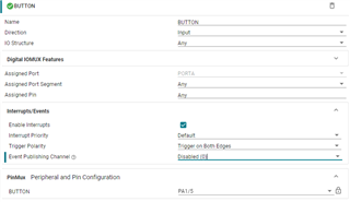
I am using a button to trigger the MSPM0L115 (28 pin variant) on PA1. This is to trigger an interrupt that wakes the MCU from sleep. Here is my config for this GPIO:

I would expect this interrupt is implemented the same as the TIMER0 IRQ I have implemented elsewhere in the design, however pressing the button does not wake the device. My relevant code is below:

    int main(void)
{
    SYSCFG_DL_init();
    NVIC_EnableIRQ(TIMER_0_INST_INT_IRQN);
    debugWrite("~ init ~\r\n");
    NVIC_DisableIRQ(TIMER_0_INST_INT_IRQN);
    NVIC_EnableIRQ(CONTROL_INT_IRQN);
    __WFI();
    NVIC_DisableIRQ(CONTROL_INT_IRQN);
    NVIC_EnableIRQ(TIMER_0_INST_INT_IRQN);
    debugWrite("~ button pressed ~\r\n");

'Control' here is the pin group I have this GPIO in. __WFI() is not passed when the button is pressed. There does not seem to be any IRQHandler prototype generated like there was for the timer 0 interrupt I have in the design, so I do not have an IRQ handler implemented, but I also don't need code to run when the button is pressed regardless. If I do not disable this timer 0, __WFI() is passed as the interrupt triggers every millisecond. I am staying in SLEEP0. I also have 'Global Wake' enabled.

I feel I am just missing some initialization call. Any ideas? 

Lastly, where can I find the documentation that covers using SysConfig generated code for this MCU? The Code Academy for this device is useful, but does not cover most features.

Thanks

Jesse

  • Hi Jesse,

    1. The configuration in Sysconfig seems to be right. Can you make sure that once you press button the voltage of PA1 has been changed?(Just want to make sure whether your hardware is ok)

    2.Sorry to say we don't have documentation about the code generated by MCU. The code is all using driverlib, and you can open the declaration of this code line.

    Regards,

    Zoey

  • Hi Zoey,

    Thanks for the reply. I have verified the button is properly connected, and outputs a falling edge when the button is pressed.

    I have found that there seems to be an interrupt triggered when I press the button, but the MCU sees it as an 'unexpected interrupt' and locks in this loop:

    /* This is the code that gets called when the processor receives an unexpected  */
    /* interrupt.  This simply enters an infinite loop, preserving the system state */
    /* for examination by a debugger.                                               */
    void Default_Handler(void)
    {
        /* Enter an infinite loop. */
        while(1)
        {
        }
    }

    Any idea why the MCU sees this as an undefined interrupt?

  • Because you don't have a handler.

    Add this code:

    /*
    * These are traps for debugging when you find that your code
    * ends up in the default handler for some unknown reason.
    * To keep the compiler from complaining, comment out the ones
    * below if you already have a working handler for that vector.
    *
    */
    void NMI_Handler(void){ __BKPT(0);}
    void HardFault_Handler(void){ __BKPT(0);}
    void SVC_Handler(void){ __BKPT(0);}
    void PendSV_Handler(void){ __BKPT(0);}
    void SysTick_Handler(void){ __BKPT(0);}
    void GROUP0_IRQHandler(void){ __BKPT(0);}
    void GROUP1_IRQHandler(void){ __BKPT(0);}
    void TIMG8_IRQHandler(void){ __BKPT(0);}
    void UART3_IRQHandler(void){ __BKPT(0);}
    //void ADC0_IRQHandler(void){ __BKPT(0);}
    //void ADC1_IRQHandler(void){ __BKPT(0);}
    void CANFD0_IRQHandler(void){ __BKPT(0);}
    void DAC0_IRQHandler(void){ __BKPT(0);}
    void SPI0_IRQHandler(void){ __BKPT(0);}
    void SPI1_IRQHandler(void){ /*__BKPT(0);*/ return;}
    void UART1_IRQHandler(void){ __BKPT(0);}
    void UART2_IRQHandler(void){ __BKPT(0);}
    void UART0_IRQHandler(void){ __BKPT(0);}
    void TIMG0_IRQHandler(void){ __BKPT(0);}
    void TIMG6_IRQHandler(void){ __BKPT(0);}
    void TIMA0_IRQHandler(void){ __BKPT(0);}
    void TIMA1_IRQHandler(void){ __BKPT(0);}
    void TIMG7_IRQHandler(void){ __BKPT(0);}
    void TIMG12_IRQHandler(void){ __BKPT(0);}
    void I2C0_IRQHandler(void){ __BKPT(0);}
    void I2C1_IRQHandler(void){ __BKPT(0);}
    void AES_IRQHandler(void){ __BKPT(0);}
    void RTC_IRQHandler(void){ __BKPT(0);}
    void DMA_IRQHandler(void){ __BKPT(0);}

    And you can at least see the name of the handler you need to add.

    There should be a gpio interrupt example you can copy.

  • Thanks Keith. Defining GROUP1 IRQ handler did the trick.