This thread has been locked.

If you have a related question, please click the "Ask a related question" button in the top right corner. The newly created question will be automatically linked to this question.

TMS570LS3137: TMS570LS3137 chip and FPGA PWM communication implementation.

Part Number: TMS570LS3137
Other Parts Discussed in Thread: HALCOGEN

Tool/software:

Dear All.

As the title says, I want to use the N2HET1[31] pin of tms570ls3137 as a PWM pin to send data to the FPGA.

I enabled HET1->Pwm0-7 -> PWM0 for the Halcogen of tms570ls3137, and set the HET pin to 31.

And I called and executed the PWM API as follows.
pwmStart(hetRAM1, pwm0);
for(uint8 i = 0; i < size; i++){
pwmSetDuty(hetRAM1, pwm0, test_telegram_table[id].data[i]);
}
pwmStop(hetRAM1, pwm0);

Actually, this seems to be the end for tms570ls3137,
but the problem is that I don't know how to implement it in FPGA.

1. If I do it according to the example source above, will the data go out as a PWM signal from tms570?

2. How do I recognize PWM data in FPGA?
Do you have something like a PWM datasheet?
It's a bit difficult because I have to implement it again according to the tms570 specifications in FPGA.

Can you help me?

Best Regards,
IBLEE

  • Hi IBLEE,

    1. If I do it according to the example source above, will the data go out as a PWM signal from tms570?

    Yes, it should generate the PWM signal.

    And I called and executed the PWM API as follows.
    pwmStart(hetRAM1, pwm0);
    for(uint8 i = 0; i < size; i++){
    pwmSetDuty(hetRAM1, pwm0, test_telegram_table[id].data[i]);
    }
    pwmStop(hetRAM1, pwm0);

    However, the signal will get generate only for "for" loop duration, once for loop timeout completed the PWM will get stop.

    I don't know what your requirement is, and i don't understand why you are trying to change the duty cycle continuously. 

    2. How do I recognize PWM data in FPGA?

    I don't know anything about FPGA,

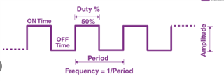
    Mainly PWM have two components Period and duty cycle, like as shown below

    Period means ON Time plus OFF Time in the cycle.

    Duty cycle means % of TON in the cycle.

    So, i don't know your requirement on FPGA side. I mean if you want to do some capturing of period and duty cycle and need to perform some action using these parameters then you can do that.

    I think you can connect this PWM to the one of the pin of FPGA and you can calculate the period and duty cycles of the waveform and can do the necessary action.

    Do you have something like a PWM datasheet?

    There won't be any special data sheet for PWM itself. In N2HET section also you can find some more additional details about PWM configurations.

    --
    Thanks & regards,
    Jagadish.

  • Dear Jagadish.

    1. Isn't the PWM function used to send byte-unit data through the PWM interface pwmSetDuty?

    Then can I use the pwmSetSignal function?

    Do you have a sample code that sends byte-unit data through PWM?

    2. I understand that I need to check the signal in the FPGA and then do the coding.

    Best Regards,
    IBLEE

  • Dear Jagadish.

    What I intend to do is to change the duty cycle and transmit the data value to the PWM signal receiver (FPGA).

    For example, when I want to send a value of 0x12, I send a duty cycle of 0x1 and a duty cycle corresponding to 0x2, and the receiver (FPGA) distinguishes between them and determines which value was received.

    That's why I changed the duty cycle, but in my opinion, the only way to transmit data with a PWM signal is to change the duty cycle. Am I thinking wrong?

    Best Regards,
    IBLEE

  • Hi IBLEE,

    1. Isn't the PWM function used to send byte-unit data through the PWM interface pwmSetDuty?

    Then can I use the pwmSetSignal function?

    Do you have a sample code that sends byte-unit data through PWM?

    The main application of PWM is to control the motor speed, usually PWM will not use for communication from controller.

    For communication purpose customers will use SCI(UART), I2C and SPI etc because these are the easy ways for communication, because if you write a byte in send register the byte automatically get shift to the Tx line in these peripherals.

    Whereas if you use PWM for communication then there is lot of overhead involved, 

    For example, i will send 25% duty cycle waveform for logic-0 in my data and similarly i will send 50% duty cycle for logic-1 in my data. And receiver should also decode this waveform and if it finds the duty cycle close to the 25% then it should treat as logic-0 and if it is 50% logic-1. You can do something like this, but it involves lot of overhead unlike UART, I2C or SPI.

    And i don't have any example for this because as i said the customers will not use PWM for data transfers between the controllers or IC's. They usually use it for intensity control or speed control etc.

    --
    Thanks & regards,
    Jagadish.