This thread has been locked.

If you have a related question, please click the "Ask a related question" button in the top right corner. The newly created question will be automatically linked to this question.

MSP432E401Y: I2C issue, MAP_I2CMasterControl sends address and a 0x00 byte

Part Number: MSP432E401Y

Tool/software:

Hello,

I have been transitioning an old code base from MSP430 to MSP432E401Y, and I've been dealing with the I2C for a bit.  I have rewritten the I2C section utilizing the i2c_master_cpu_fifo_MSP_EXP432E401Y_nortos_ccs example.  I have found an issue though, in this otherwise working I2C code I've been working on.  It sends an extra 0x00 byte that is not needed whenever I use MAP_I2CMasterControl to prepare to write.

Using the following breakpoints:

I can see the following:
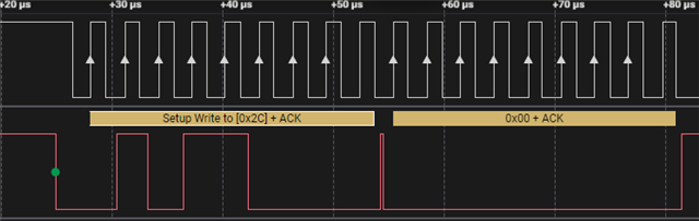

I wouldn't expect the call to I2C Master Control to send anything.  Should I have different arguments, or is there some flag I need to set or something to ensure that nothing is written except for the data I put on the queue with MAP_I2CFIFODataPutNonBlocking?


Thank you for your help in advance.

  • Hi,

      MAP_I2CMasterControl is what starts the I2C state machine. When you use I2C_MASTER_CMD_BURST_SEND_START, it means it begins with the first write data of a burst sequence. After the first data is sent, you are holding the bus idle until subsequent data are sent. The subsequent data are sent using the I2C_MASTER_CMD_BURST_SEND_CONT and the last data in the burst sequence is ended with the I2C_MASTER_CMD_BURST_SEND_FINISH. 

    If you only have one data to write, then you should be using an example as follows using the I2C_MASTER_CMD_SINGLE_SEND flag.

    MAP_I2CMasterControl(I2C7_BASE I2C_MASTER_CMD_SINGLE_SEND);

    Below is an example code to read multiple data. You can mimic the code for the write operation. 

    void
    I2CReadCommand(uint32_t * pui32DataRx)
    {
    //
    // Modify the data direction to true, so that seeing the address will
    // indicate that the I2C Master is initiating a read from the slave.
    //
    MAP_I2CMasterSlaveAddrSet(I2C7_BASE, SHT21_I2C_ADDRESS, true);

    //
    // Setup for first read. Use I2C_MASTER_CMD_BURST_RECEIVE_START
    // to start a burst mode read. The I2C master continues to own
    // the bus at the end of this transaction.
    //
    MAP_I2CMasterControl(I2C7_BASE, I2C_MASTER_CMD_BURST_RECEIVE_START);

    //
    // Wait until master module is done transferring.
    // The I2C module has a delay in setting the Busy flag in the register so
    // there needs to be a delay before checking the Busy bit. The below loops
    // wait until the Busy flag is set, and then wait until it is cleared to
    // indicate that the transaction is complete. This can take up to 633 CPU
    // cycles @ 100 kbit I2C Baud Rate and 120 MHz System Clock. Therefore, a
    // while loop is used instead of SysCtlDelay.
    //
    while(!MAP_I2CMasterBusy(I2C7_BASE))
    {
    }
    while(MAP_I2CMasterBusy(I2C7_BASE))
    {
    }

    //
    // Read the first byte data from the slave.
    //
    pui32DataRx[0] = MAP_I2CMasterDataGet(I2C7_BASE);

    //
    // Setup for the second read. Use I2C_MASTER_CMD_BURST_RECEIVE_CONT
    // to continue the burst mode read. The I2C master continues to own
    // the bus at the end of this transaction.
    //
    MAP_I2CMasterControl(I2C7_BASE, I2C_MASTER_CMD_BURST_RECEIVE_CONT);

    //
    // Wait until master module is done transferring.
    //
    while(!MAP_I2CMasterBusy(I2C7_BASE))
    {
    }
    while(MAP_I2CMasterBusy(I2C7_BASE))
    {
    }

    //
    // Read the second byte data from the slave.
    //
    pui32DataRx[1] = MAP_I2CMasterDataGet(I2C7_BASE);

    //
    // Setup for the third read. Use I2C_MASTER_CMD_BURST_RECEIVE_FINISH
    // to terminate the I2C transaction. At the end of this transaction,
    // the STOP bit will be issued and the I2C bus is returned to the
    // Idle state.
    //
    MAP_I2CMasterControl(I2C7_BASE, I2C_MASTER_CMD_BURST_RECEIVE_FINISH);

    //
    // Wait until master module is done transferring.
    //
    while(!MAP_I2CMasterBusy(I2C7_BASE))
    {
    }
    while(MAP_I2CMasterBusy(I2C7_BASE))
    {
    }

    //
    // Note the third 8-bit data is the checksum byte. It will be
    // left to the users as an exercise if they want to verify if the
    // checksum is correct.
    pui32DataRx[2] = MAP_I2CMasterDataGet(I2C7_BASE);

  • Thank you for the response, but that's not quite what I want to do.

    I want to send several bytes, which I send using MAP_I2CFIFODataPutNonBlocking in the state machine.  I would not like a zero byte to be sent after the address.  Why does it send a zero after I call MAP_I2CMasterControl?  Is there a way to cause it to write the first byte of my data rather than a zero?

    I don't understand why a zero byte specifically is sent.


    Currently, with my code if I try to send a {1F,FF} to 0x2C, I actually send 0x00 as soon as the MasterControl is called, then 1F,FF.  How can I get this to send just 1F,FF?

    Thank you again for your time.

  • Here is my feedback.

     - Did you flush the FIFO? It is possible that some residual already in the FIFO.

     - If you are going to use FIFO then you would need the I2C_MASTER_CMD_FIFO_BURST_SEND_START flag but you use I2C_MASTER_CMD_BURST_SEND_START instead which is a call for non-FIFO operation.

     -  I strongly advice you not use the FIFO version in your initial development. Once you get the basic working, you are free to try out the FIFO. 

     - I never use MAP_I2CFIFODataPutNonBlocking myself. I always use I2CFIFODataPut to prepare each data to send before calling MAP_I2CMasterControl.

  • I rewrote the code calling the non FIFO functions.  The sample code does call I2C_MASTER_CMD_BURST_SEND_START and then uses the FIFO calls, however.  After rewriting it from scratch rather than using the examples, I have the code working entirely.  Thanks for your help