This thread has been locked.

If you have a related question, please click the "Ask a related question" button in the top right corner. The newly created question will be automatically linked to this question.

TMS570LC4357: Description of I2CPDR correct?

Part Number: TMS570LC4357
Other Parts Discussed in Thread: HALCOGEN

Tool/software:

Hi experts,


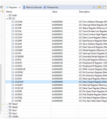
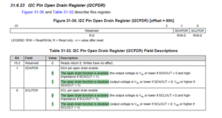
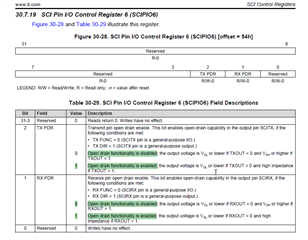
In the description of the I2CPDR register (Table 31-32) in the Technical Reference Manual, the bits are described as follows:

SCLPDR:

0 - Open drain function is enabled
1 - Open drain function is disabled

This differs from the description in other PDR registers (e.g. Table 25-19. GIOPDR). Normally a setting of 0 disables open drain and enables push/pull and a setting of 1 enables open drain.

  1. Is this an error in the description of the i2CPDR register or is the configuration for this register different?
  2. Is there no push/pull functionality?

Thanks and best regards,
Max

  • Hi Max,

    Actually, datasheet was correct only,

    I mean PDR bit value 0 means the corresponding pin's open drain is enabled. And if the PDR bit value 1 means the corresponding pins open drain is disabled.

    And i also found that the HALCoGen also generating the code in reverse order, i mean HALCoGen GUI and generated code not matching for PDR.

    I will explain this in detail in my next comment.

    --
    Thanks & regards,
    Jagadish.

  • Hi Max,

    To do this testing i configured the pins as below:

    Mainly i want to disable the internal pull-up or pull-down, because the main difference between open drain enable and open drain disable is that when we disable the open drain then whatever the value (Logic-0/Logic-1) written on the DOUT register will get forwarded to the output GIO pin and also refects the same on DIN register.

    Whereas if you enable the open drain then logic-0 will properly transmit to the output GIO pin and also reflects on DIN register but if you try to write Logic-1 then the pin will be in high state, and an external or internal pull will give the result now.

    After doing above configurations, here are my test results:

    1. Disabling Open drain and writing Logic-0:

    So as i disabled open drain and written the logic-0 i got the same value on DIN

    And also, my GIO output pin values are also logic-0 only.

    2. Disabling Open drain and writing Logic-1:

    Similarly, when i disabled open drain and write logic-1 i got the same value in DIN

    And my GIO output value also reflecting the same:

    3. Enabling Open drain and writing Logic-0:

    As we discussed earlier, for open drain enable case also logic-0 will get properly transmitted to the output GIO pin and DIN register.

    So, the same behavior was reflected:

    4. Enabling Open drain and writing Logic-1:

    This is the important condition, and this is where the output should be in high impedance state. As you can see even though i write logic-1 on the DOUT register, it is showing logic-0 in DIN register. This is because of high impedance state.

    And you can also see logic analyzer output also, it is also showing no voltage on GIO pin:

    So, as you can see the high impedance state or open drain condition occurs when the PDR value becomes zero right. That means datasheet description was correct:

    --
    Thanks & regards,
    Jagadish.

  • Hi Max,

    I also found a mistake with HALCoGen GUI and generated code:

    1. As you can see i didn't enable the open-drain checkboxes in HALCoGen, that means open drain is in disabled state according to the GUI right?

    However, if you verify the generated code, it is writing logic-0 to the PDR register for both SDA and SCL, that means it is enabling the open drain as per the tastings in my last comment.

    2. Similarly, now i am enabling the open drain according to the HALCoGen GUI:

    Now it is writing logic-1 to the PDR register, that means open drain disable according to datasheet and our testing results.

    I am also suspecting that, may be in silicon hardware level they implemented in reverse, because if you verify the other peripherals PDR registers like SCI and MibSPI etc.

    Usually writing logic-1 will enable the open-drain and writing logic-0 will disable the open drain, however for this i2c peripheral it is working in reverse. So, there might be some issue in hardware that is the reason maybe they reversed the description.

    --
    Thanks & regards,
    Jagadish.

  • Hi Max,

    And one more very important thing is that the above HALCoGen issue or silicon hardware issue doesn't affect the behavior of the i2c.

    Because if the SDA or SCL pins are configured as i2c functionality then irrespective of the value of PDR register the pins will always act as open drain. Ony when these pins were configured as GIO then only this issue comes into the picture.

    --
    Thanks & regards,
    Jagadish.

  • Hi Jagadish,

    Thank you for the quick and detailed reply.

    Thank you and best regards,
    Max