Other Parts Discussed in Thread: SYSCONFIG,
Tool/software:
Hi Team,
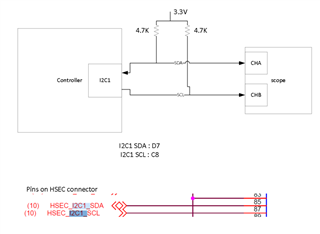
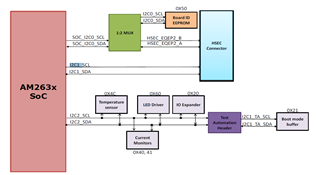
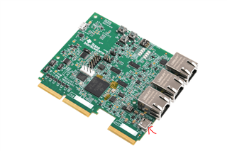
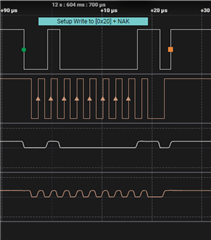
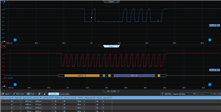
I have interfaced I2C based digipot to I2C2. I am using code from resource explorer "i2c_read_am263x-cc_r5fss0-0_nortos_ti-arm-clang". However, not able to see any output on scope for both the pins.
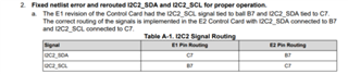
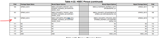
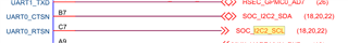
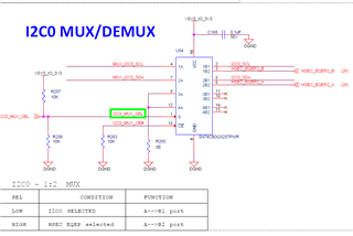
SDA pin : C6
SCL pin: A5
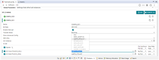
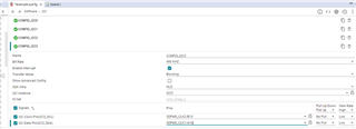
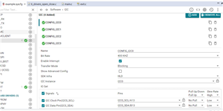
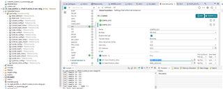
I2C2 configuration is given below
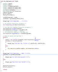
Code:
void i2c_read_main(void *arg0)
{
uint16_t sample;
int32_t status;
uint32_t i2cReadTargetAddr;
uint8_t rxBuffer[I2C_READ_LEN];
uint8_t txBuffer[I2C_WRITE_LEN];
I2C_Handle i2cHandle;
I2C_Transaction i2cTransaction;
Drivers_open();
Board_driversOpen();
i2cReadTargetAddr = Board_i2cGetEepromDeviceAddr();
i2cHandle = gI2cHandle[CONFIG_I2C1];
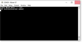
DebugP_log("[I2C] Read data ... !!!\r\n");
txBuffer[0]=1;
/* Set default transaction parameters */
I2C_Transaction_init(&i2cTransaction);
/* Override with required transaction parameters */
i2cTransaction.readBuf = rxBuffer;
i2cTransaction.readCount = I2C_READ_LEN;
i2cTransaction.targetAddress = i2cReadTargetAddr;
i2cTransaction.writeCount= I2C_WRITE_LEN;
i2cTransaction.writeBuf= txBuffer;
/* Read 20 samples and log them */
for(sample = 0; sample < 20; sample++)
{
status = I2C_transfer(i2cHandle, &i2cTransaction);
if(status == I2C_STS_SUCCESS)
{
DebugP_log("[I2C] Sample %u: %u\r\n", sample, rxBuffer[0]);
}
else
{
i2c_read_error_handler(sample, i2cTransaction.status);
}
}
DebugP_log("[I2C] Read data ... DONE !!!\r\n");
if(status == SystemP_SUCCESS)
{
DebugP_log("All tests have passed!!\r\n");
}
else
{
DebugP_log("Some tests have failed!!\r\n");
}
Board_driversClose();
Drivers_close();
return;
}
Please let me know if I am missing any configuration or code change.
Appreciate your help!