This thread has been locked.
If you have a related question, please click the "Ask a related question" button in the top right corner. The newly created question will be automatically linked to this question.
Tool/software:
Hi,
The Hercules TRM states:
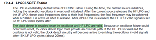
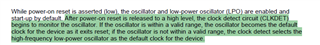
10.4.4 LPOCLKDET Enable The LPO is enabled by default while nPORRST is low. During this time, the current source initializes, holding the relaxation oscillator in reset until initialized. After the current source releases the HF LPO and the LF LPO, these clock frequencies slew to their final frequencies; the final frequency may be achieved while nPORRST is active or after its release. After, nPORRST is released, the HF LPO Valid signal is set 32 HF LPO clock cycles later. The clock detect is enabled once the oscillator and HF LPO are valid. Because an oscillator failure could occur from reset, the clock detect logic must provide an override path. If the HF LPO is valid and the oscillator is not valid, the clock detect circuitry will become active (overriding the oscillator invalid signal) after 16K LF LPO cycles (about 200ms)
However, if I short the OSCIN pin to ground and try to do RST/PORRST/power cycle, the MCU does not seem to start.
May someone provide insight regarding:
Thanks!
Hi Varban,
Maybe we should need to comment the certain clock related initializations in startup.c file to run the code with LPO.
I think the below highlighted functions will create issue if you directly execute your code with LPO,
This is because, setupPLL is not possible because of our oscillator clock not generating but in our clock configurations we mentioned that oscillator clock as PLL input:
And also, trimLPO is not possible because, LPO is the only clock now driving the code execution, so we cannot trim the clock while executing code.
Similarly, mapClocks also will not possible as PLL are no use now.
I created one example LED blinky project with above modifications and also few other modifications. I am attaching my project here for your reference:
In this project the LED's are blinking even after i shorted OSC pin to ground and pressing Power On Reset.
--
Thanks & regards,
Jagadish.
Hi Jagadish,
Thanks for the example and the directions.
Narrowing down the scope of your suggestion after several hours of debugging, I got it working only by playing with the value of the CLKTEST register inside void trimLPO(void). The following attempts have been done:
/* USER CODE BEGIN (4) */ systemREG1->SYSPC1 |= (uint32)((uint32)0x1U << 0U); /* Set the ECPCLKFUN to enable the clock on the ECLK pin */ // // Bit 19 - 16 pattern is default: 1010 // // // Experiment with bits 25 - 24 // // systemREG1->CLKTEST = 0b00000001000010100000000000000000; /* Should be the default, fails to start with LPO after reset */ /* TRM: The range detect enable is controlled by the RANGEDETCTRL bit (Bit 25) of the CLKTEST register. The clock monitor range detection circuitry (RANGEDETECTENABLE) is disabled. */ // systemREG1->CLKTEST = 0b00000000000010100000000000000000; /* Works perfectly */ /* TRM: The range detect enable is generated by the hardware in the clock monitor wrapper. */ // systemREG1->CLKTEST = 0b00000011000010100000000000000000; /* Works perfectly */ /* TRM: The range detect enable is controlled by the RANGEDETCTRL bit (Bit 25) of the CLKTEST register. The clock monitor range detection circuitry (RANGEDETECTENABLE) is enabled. */ // // Experiment with bit 19 - 16 pattern: 0000 (no change on the ECLK pin, same as with 1010) // // systemREG1->CLKTEST = 0b00000001000000000000000000000000; /* Should be the default, again, fails to start with LPO after reset */ /* TRM: The range detect enable is controlled by the RANGEDETCTRL bit (Bit 25) of the CLKTEST register. The clock monitor range detection circuitry (RANGEDETECTENABLE) is disabled. */ // systemREG1->CLKTEST = 0b00000000000000000000000000000000; /* Again, works perfectly */ /* TRM: The range detect enable is generated by the hardware in the clock monitor wrapper. */ systemREG1->CLKTEST = 0b00000011000000000000000000000000; /* Again, works perfectly */ /* TRM: The range detect enable is controlled by the RANGEDETCTRL bit (Bit 25) of the CLKTEST register. The clock monitor range detection circuitry (RANGEDETECTENABLE) is enabled. */ /* USER CODE END */
As mentioned in the code snippet comments, four of the options work properly and I start directly with the LPO after reset, keeping the peripherals clocked properly. However, it is not clear to me which one is the safest. More specifically, regarding:
Another interesting place is void setupPLL(void) with the while loop:
/* Disable PLL1 and PLL2 */ systemREG1->CSDISSET = 0x00000002U | 0x00000040U; /*SAFETYMCUSW 28 D MR:NA <APPROVED> "Hardware status bit read check" */ while((systemREG1->CSDIS & 0x42U) != 0x42U) { /* Wait */ }
3.In case of power-on with failed main oscillator and relying only on the LPO, is it guaranteed that it will always fulfill the condition and never loop to infinity?
Thanks and regards,
Varban
Hi Varban,
If clock detection is disabled, then switchover from OSC to LPO will not takes place. That means, even if the oscillator failed switching will not takes place and still oscillator clock will try to drive the core and that means code execution will not happen.
Same thing (clock detection disabled) is happening in your all the failed conditions.
RANGEDETENASSEL = 1 and RANGEDETCTRL = 0 :
In this case clock detection circuit is disabled, so that means if the oscillator failed then switchover to the LPO clock will not happen and the code execution will get fail.
RANGEDETENASSEL = 1 and RANGEDETCTRL = 1 :
In this case clock detection circuit is enabled, that means if the oscillator failed then switchover to the LPO will takes place. That is the reason code execution happens correctly.
RANGEDETENASSEL = 0 and RANGEDETCTRL = X :
In this case the clock detection or range detection is generated by hardware, i mean in previous two conditions software controlled the clock detection circuit right but in this case the hardware itself generates the clock detection.
That means for this device after power on reset released the by default the hardware will enable the clock detection. So that means in this condition also switchover to LPO will take place if oscillator gets fail. That is the reason in this condition also it is worked without any issues.
--
Thanks & regards,
Jagadish.
Hi Jagadish,
i mean in previous two conditions software controlled the clock detection circuit right but in this case the hardware itself generates the clock detection
In what sense does the software control the clock detection circuit? And what are the pros/cons of each approach?
Thanks!
Hi Varban,
Apologies for the delay in late response, i am on leave for couple of days.
In what sense does the software control the clock detection circuit? And what are the pros/cons of each approach?
There won't be any performance differences in both the cases.
The only difference is that, in hardware case it is taking the default state of the clock detection. The software method will only require if we want to disable the clock detection.
--
Thanks & regards,
Jagadish.
Hi Jagadish,
Alright, thanks a lot for your help and informative replies!
-Varban