This thread has been locked.

If you have a related question, please click the "Ask a related question" button in the top right corner. The newly created question will be automatically linked to this question.

TMS570LS1224: SCI clock after enabling PLL modulation

Part Number: TMS570LS1224
Other Parts Discussed in Thread: HALCOGEN

Tool/software:

Hi,

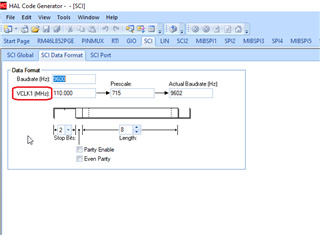
When enabling the modulation option of the PLL (configured to deliver 10MHz to the GCM), my SCI port would no longer send the proper characters to the terminal.

Is this normal and is there a way to debug it, so that I can know what clock compensation I need to adjust in order to get peripheral clocks work normally?

  • Hi Varban,

    SCI baudrate will be generated based on the VCLK1 frequency.

    For example, assume that you configured GCLK as 220Mhz and VCLK1 as 110Mhz in HALCoGen on GCM module like as shown below:

    Now if you change the clock source of GCLK at run time then your VCLK1 frequency will also get down (all multipliers and dividers of the clock will not change). For example, i changed GCLK to 10Mhz then our VCLK1 will become 5Mhz.

    As you can see if i apply 5Mhz clock with same prescaler value then my SCI baudrate comes down to the 438 from 9600.

    So, keep this in mind and change the prescaler in according to the changed clock frequency.

    --
    Thanks & regards,
    Jagadish.

  • Hi Jagadish,

    Thanks again for your quick response. Maybe I did not provide a detailed description of the issue I am experiencing. 

    So, I have configured the PLL output to be 10MHz, equal to the LPO. Upon oscillator failover from the main ext. oscillator to the LPO, my UART continues working properly, at the same baud rate and I read the expected characters.

    However, when I do the following register change to enable the oscillator modulation

    // From
    systemREG1->PLLCTL2 |= 0x00000000U;
    
    // To
    systemREG1->PLLCTL2 |= 0x80000000U;

    although the SCI baud rate value does not change visually (in HALCoGen), my UART gets messy.

    So, upon enabling the modulation, the frequency that is feeding the GCM seems to change. Or at least my configuration is not proper for 10MHz (I mean the Spreading Amount, Multiplier Correction and Spreading Rate params).

    Are there any application notes about this topic?

    And can I expose the PLL1 frequency to the ECLK pin?

    Thanks,

    Varban

  • Hi Varban,

    Apologies for the delay in late response, i am on vacation for few days and also followed by weekend.

    May i know why you are trying to use PLL modulation.

    I never used this modulation before, however according to TRM if we enable the modulation then base frequency is going to vary like as mentioned below:

    If the frequency varies then there is a chance of varying in baudrate of UART and may be UART will get messy.

    --
    Thanks & regards,
    Jagadish.

  • Hi Jagadish,

    May i know why you are trying to use PLL modulation.

    Well, because the MCU is about to operate in really noisy environment and I expect that using PLL modulation will increase the overall stability...

    TRM if we enable the modulation then base frequency is going to vary like as mentioned below:

    Indeed, but I still cannot figure out how to interpret the HALCoGen parameters (namely Spreading Amount, Multiplier Correction and Spreading Rate) in regard to the formula(s) described in the TRM, so that I can calculate the frequency after enabling the modulation.

    Thanks!

  • Hi Varban,

    You are correct the modulation reduces the electromagnetic radiation impatct.

    However, it will impact all other peripheral frequencies as well like as mentioned in below thread:

    (+) TMS570 PLL modulation - Arm-based microcontrollers forum - Arm-based microcontrollers - TI E2E support forums

    So, to reduce this impact we should need to adjust the depth of the modulation as mentioned in above thread. So, try to decrease depth of the modulation and test it again.

    --
    Thanks & regards,
    Jagadish.

  • Hi Jagadish,

    Thank you for your reply.

    I am still confused regarding the "mapping" of the parameters in the datasheet formulas and the register fields in PLLCTL2 (please refer to the attached image).

    It is obvious where the NS and NV derive from, but what about NR, R and NF? Without NF, there is no way to calculate the depth percentage. 

    And what is the meaning of those parameters?

    Thanks!

  • Hi Varban,

    You can find these parameters easily in the HALCoGen:

    Open PLL section and move the controller to the different dividers and multipliers and see the corresponding notations.

    --
    Thanks & regards,
    Jagadish.

  • Thanks, Jagadish! It's much clearer now.

    And one last (a bit off-topic) question - what Windows and screen resolution are you using for the screenshots? HALCoGen looks amazingly well, like in the old days.

    For comparison, this is my user interface experience (everything is misleadingly misplaced):

  • Hi Varban,

    The below is my display resolution:

    And also, i am using Greenshot for the screenshots instead of default snipping tool:

    --
    Thanks & regards,
    Jagadish.