This thread has been locked.

If you have a related question, please click the "Ask a related question" button in the top right corner. The newly created question will be automatically linked to this question.

AM263P4-Q1: ADC_R0 and ADC_R1 SOC signal

Part Number: AM263P4-Q1
Other Parts Discussed in Thread: SYSCONFIG

Tool/software:

Hi BU,

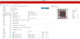
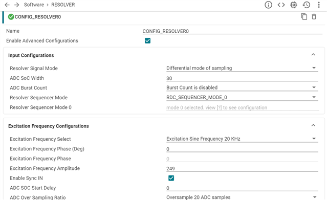
I have downloaded the AM263Px MCU+SDK.I have imported the example called "resolver_angle_speed_am263px-cc_r5fss0-0" from SDK and only modified the signal mode(from single mode to differential mode). The input signal of ADC_R0_AIN[1:0] and ADC_R1_AIN[1:0] are the reference sine and cosine signals. I found that the conversion data read from register is still 0, which was not correct. I didn't find the SOC for ADC_R0 and ADC_R1 in reference manual. Could you please tell me how to solve this problem? In addition, what does the field "CAL_CHSEL" in register "*0x502CB024" mean? Thank you very much.

  • Hi Yuxin Liu,

    In AM263P, we have Resolver, that uses ADC_R Front End for RDC sampling on Sine an Cosine Channels. the same Front end is used for ADC_R digital wrapper as well. so if we are using the ADC_R we should not configure Resolver, in the same way if we are using Resolver, we cannot use the ADC_R digital wrapper. 

    Now, ADC_R digital wrapper includes the Result registers you are talking about. 

    If you are looking to ADC_R as ADC, please use it by configuring it like any other ADC you would normally use. Only difference from ADC_Rs to ADCs in AM263P are the following,

    • 3.125MSPS 
    • 4 Channels in all
    • Safety Tiles are not Enabled.

    you can also try checking the syscfg as shown below

    Thanks and regards,

    Madhava

  • Hi Madhava,

    Thank you for your fast response. So, did you mean that if I want to use resolver, I shouldn't configure the ADC_R in Sysconfig? Because when I imported the resolver example from SDK, I found only resolver was configured and left ADC_R unconfigured. However, when I run the example, the calculation results were not correct. The inputs on ADC_R0 and ADC_R1 are the reference sine and cosine signals. Here shows the configuration from my side.(Advanced configuration left default). Thank you very much!

    Best regards,

    Yuxin Liu