This thread has been locked.

If you have a related question, please click the "Ask a related question" button in the top right corner. The newly created question will be automatically linked to this question.

TMDX570LC43HDK: TMS570LC43x on a Custom Board

Part Number: TMDX570LC43HDK
Other Parts Discussed in Thread: TMS570LC4357,

Tool/software:

Good afternoon,

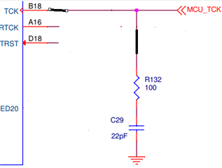
I am currently working on a custom board featuring the TMS570LC4357 microcontroller and have encountered an issue when attempting to connect it to Code Composer Studio (CCS). Specifically, I receive a "cable break" error.

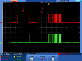
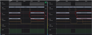
I have verified that my custom board uses the same FTDI chip as the evaluation board. However, despite this similarity, my board fails to connect properly. I have analyzed the signal data from both the evaluation board and my custom board using Saleae Logic 2 software. The results indicate a failure during the connection process on my custom board.

Could there be any specific checks or configurations in CCS that might not be compatible with my custom board? I have attached the signal readings for your reference.

Left - Custom Board; Right - Evaluation Board

I appreciate any guidance or insights you can provide.

Best regards,

Miguel Catana

  • Hi Miguel Catana,

    We are working on your issue now and will try to provide our updates ASAP.

    --
    Thanks & regards,
    Jagadish.

  • Hello Jagadish,

    I am working with Miguel catana on this issue.

    I just want to clarify some details to help describe the issue.

    On the image provided on the left side is the JTAG signals on our custom board. On the right side is the signals measured on the TMDX570LC43HDK  development kit. 

    The hardware schematic is very similar to the schematic of the develpment kit (same pull-ups and connections). The main difference is that we do not have the CPLD between the FTDI and the MCU.

    The error occuring is on the "Test Connection" procedure. From the sequence of the test described in the code composer studio windown it seems to be failing with the test to write 0x00000000 (64 block of 32 bit). This i where the indication o the "cable break" error occurs.

    Thank you very much for the support.

    Best regards,

    Luís Aguiar

  • Hello Jagadish,

    It is possible for us to have access to the CPLD design? the project or at least a description of the logic in the CPLD could help us understand the differences better.

    Best regards,

    Luís Aguiar

  • Hi Luis Aguiar,

    I am sorry we don't have the source code for CPLD. This source code is part of XDS100V2 emulator, please check ti emulator support page:

    https://processors.wiki.ti.com/index.php/XDS100

    --
    Thanks & regards,
    Jagadish.

  • Hello Jagadish,

    Thank you for the information on the XDS100.

    We did some test on our side and found the following.

    Measuring the signal on the FT2232HL and the MCU side on the  TMDX570LC43HDK development board we see a slightly different behavior of the TDO line (see image bellow, red JTAG_TDO on FT2232HL side, green JTAG_TDO on MCU side).

    We assume it has something to do with the Adaptive clocking feature of the FT2232HL that could drive the TDO signal. is this correct? We also see this on our custom board.

    Could this be causing issue with the "Test connection" procedure?

    Is it possible to disable this adaptive clocking from the code composer studio? or does it require some different method?

    Is the CPLD an absolute requirement for the XDS100 debug/programmer? or it would also work without the CPLD?  

    Is there any detailed description of the "Test Connection" procedure?

    If it helps understanding of the capture we have logic analyzer captures that we did on both the custom and TMDX570LC43HDK (Using Saleae Logic software) that we can provide you. What would be the best option for us to provide you with the files? 

    Best regards,

    Luis Aguiar

  • Hi Luis,

    I am assigning this issue to my senior colleague QJ, who have more experience in JTAG. Hopefully he will respond in soon.

    --
    Thanks & regards,
    Jagadish.

  • Hi Luis,

    The CPLD is required for xds100V2. 

  • Hello QJ,

    Thank you for the information.

    So we can assume the reason it fails the Test connection is due to the CPLD is not being used on our custom board. Is this correct?

    We are waiting to arrive a XDS200 debug emulator and we will attempt to externally program the MCU over a JTAG connector.

    I will keep you informed if we still experience any issues.

    Best regards,

  • Hi,

    Most likely the problem is related to the CPLD.

    If you like to add an emulator on your PCB board, xds110 is a better option which is used on tms570lc43x launchpad.

    https://www.ti.com/tool/LAUNCHXL2-570LC43

  • Hello QJ,

    We have tested the board with the external programmer XDS200 and it works correctly.

    Thank you very much for the suggestion ofthe XDS110. i assume the source code is provided. correct?

    During our internal discussion on this issue some questions came up:

    1. Is there a replacement for the CPLD? The current is indicated as End-Of-Life. does is come with a design to program?

    2. Would it still be possible to for us to still use the FT2232HL and to make our own proprietary software to handle the MCU programming without "adaptive clocking" or the MCU requires "adaptive clocking" for the comminication?

    3. We are considering adding two other devices to the JTAG Daisy chain (two FPGA's) would there be any issues? can you provide us with an example of how to setup the daisy chain on code composer studio?

    Best regards,

  • i assume the source code is provided. correct?

    The driver (programed to tm4c129 flash) is located in CCS installation folder. It is a binary file.The ROM USB bootloader will download the binary file to internal flash.

    C:\ti\ccs1270\ccs\ccs_base\common\uscif\xds110

    1. Is there a replacement for the CPLD? The current is indicated as End-Of-Life. does is come with a design to program?

    We stopped using xds110v2 in new TI launchpad and EVM. XDS110 is widely used on TI launchpad. XDS110 uses TM4C129 MCU instead of FTDI chip and CPLD.

    2. Would it still be possible to for us to still use the FT2232HL and to make our own proprietary software to handle the MCU programming without "adaptive clocking" or the MCU requires "adaptive clocking" for the comminication?

    If you use your own proprietary software, how do you make it compatible with TI code composer studio?

    3. We are considering adding two other devices to the JTAG Daisy chain (two FPGA's) would there be any issues? can you provide us with an example of how to setup the daisy chain on code composer studio?

    Emulation and Trace Headers Technical Reference Manual (Rev. I)

  • Hello QJ,

    Thank you for the information.

    If you use your own proprietary software, how do you make it compatible with TI code composer studio?

    The proprietary software would be used to only program the MCU and the FPGA's (no debugging functionality). Is there some API that would allow our software to interact with the with the FT2232HL or XDS110 or XDS200 debug probes?

    This is to improve our testing, maintenance and production procedures to avoid the need for three different softwares (and cables) for uploading the MCU and the two different FPGA's.

    Emulation and Trace Headers Technical Reference Manual (Rev. I)

    On the code composer studio when it attempts the a "Test connection" on the JTAG it fails when we have the two FPGA's on the chain. We assume that is because the Code composer studio is expecting only the MCU on the chain. Is there a way we can indicate there are the two FPGA's and bypass them? 

  • Is there some API that would allow our software to interact with the with the FT2232HL or XDS110 or XDS200 debug probes?

    I don't know the APIs of XDS110 or XDS200.

    You can use an external emulator for debugging in development stage, and use bootloader (Ethernet, UART, CAN, SPI, etc) to update the firmware.

    Is there a way we can indicate there are the two FPGA's and bypass them? 

    I don't have experience of using JTAG Daisy chain.

  • Hi,

    Just double check the JTAG signal connections in your JTAG daisy-chain setup.

    The TCK, TMS and nTRST signals must be connected in parallel to all devices connected to the daisy-chain. nTRST signal should be pulled down to GND via a resistor (for example 10kohms). It's nice to have a low pass filter (R-C filter) on nTRST at JTAG header to prevent the noise. 

    The TCK signal is particularly sensitive to reflections. It should be kept very short with no stubs when routing from JTAG connector then to first device then to 2nd/3rd device. Using an AC termination at the last device is a good idea. The AC termination is a small resistor and a capacitor in series to GND. 

    The TDI and TMS should be pulled high (3.3V) with 10Kohms resistors. Each device's TDO should be pulled down to GND with a 10kohm resistor. It's better to have a series resistor (for example 22ohms or 33ohms) on the TDO of the last device in the daisy-chain.

    It is important that you avoid cross talk on all JTAG signals. This is usually an issue in the cabling, not so much in board layout. 

  • Hello QJ,

    Thank you very much for the information. it was very useful. we have configured the Daisy chain on the CCS based on link you provided and now we have it working.

    We will do several more tests but all seems to have been resolved.

    Thank you very much for your support.

    Best regards,

  • It's nice hearing you have resolved the issue. Thank you!