This thread has been locked.

If you have a related question, please click the "Ask a related question" button in the top right corner. The newly created question will be automatically linked to this question.

MSP432E401Y: How to manually control ALE in EPI HB16 mode

Part Number: MSP432E401Y
Other Parts Discussed in Thread: MSP-EXP432E401Y

Tool/software:

Hello Team,

As in below image, MSP432 and CPLD are connected. This is done with reference to the www.ti.com/.../TIDM-TM4CFLASHSRAM
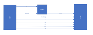
In our custom board, we tried HB8 ADNOMUX quad CS mode with the available connections, EPI is working fine. Data and address are perfect. We have also made HB16 ADNOMUX in MSP-EXP432E401Y launchpad and CPLD's EVK, this is also working fine but in our custom board we have it connected as in above image.

I'm trying to read and write data from CPLD in HB16 ADMUX mode with ALE and Quad CS mode but since it is connected to latch,  i could only see data in the address pins as well.(checked with Integrated logic analyzer in CPLD tool).

Please find the code below

 MAP_SysCtlPeripheralEnable(SYSCTL_PERIPH_GPIOA);
          MAP_SysCtlPeripheralEnable(SYSCTL_PERIPH_GPIOB);
          MAP_SysCtlPeripheralEnable(SYSCTL_PERIPH_GPIOC);
          MAP_SysCtlPeripheralEnable(SYSCTL_PERIPH_GPIOG);
          MAP_SysCtlPeripheralEnable(SYSCTL_PERIPH_GPIOH);
          MAP_SysCtlPeripheralEnable(SYSCTL_PERIPH_GPIOK);
          MAP_SysCtlPeripheralEnable(SYSCTL_PERIPH_GPIOL);
          MAP_SysCtlPeripheralEnable(SYSCTL_PERIPH_GPIOM);
          MAP_SysCtlPeripheralEnable(SYSCTL_PERIPH_GPIOP);
          MAP_SysCtlPeripheralEnable(SYSCTL_PERIPH_GPIOQ);
          MAP_SysCtlPeripheralEnable(SYSCTL_PERIPH_GPION);


          MAP_GPIOPinConfigure(GPIO_PH0_EPI0S0);
          MAP_GPIOPinConfigure(GPIO_PH1_EPI0S1);
          MAP_GPIOPinConfigure(GPIO_PH2_EPI0S2);
          MAP_GPIOPinConfigure(GPIO_PH3_EPI0S3);
          MAP_GPIOPinConfigure(GPIO_PC7_EPI0S4);
          MAP_GPIOPinConfigure(GPIO_PC6_EPI0S5);
          MAP_GPIOPinConfigure(GPIO_PC5_EPI0S6);
          MAP_GPIOPinConfigure(GPIO_PC4_EPI0S7);
          MAP_GPIOPinConfigure(GPIO_PA6_EPI0S8);
          MAP_GPIOPinConfigure(GPIO_PA7_EPI0S9);
          MAP_GPIOPinConfigure(GPIO_PG1_EPI0S10);
          MAP_GPIOPinConfigure(GPIO_PG0_EPI0S11);
          MAP_GPIOPinConfigure(GPIO_PM3_EPI0S12);
          MAP_GPIOPinConfigure(GPIO_PM2_EPI0S13);
          MAP_GPIOPinConfigure(GPIO_PM1_EPI0S14);
          MAP_GPIOPinConfigure(GPIO_PM0_EPI0S15);
          MAP_GPIOPinConfigure(GPIO_PL0_EPI0S16);
          MAP_GPIOPinConfigure(GPIO_PL1_EPI0S17);
          MAP_GPIOPinConfigure(GPIO_PL2_EPI0S18);
          MAP_GPIOPinConfigure(GPIO_PL3_EPI0S19);//parallel flash
          MAP_GPIOPinConfigure(GPIO_PQ0_EPI0S20);//parallel flash
          MAP_GPIOPinConfigure(GPIO_PQ1_EPI0S21);//parallel flash
          MAP_GPIOPinConfigure(GPIO_PQ2_EPI0S22);//parallel flash
          MAP_GPIOPinConfigure(GPIO_PQ3_EPI0S23);//parallel flash
          MAP_GPIOPinConfigure(GPIO_PK7_EPI0S24);
          MAP_GPIOPinConfigure(GPIO_PK6_EPI0S25);
          MAP_GPIOPinConfigure(GPIO_PL4_EPI0S26);//cs0 parallel flash
          MAP_GPIOPinConfigure(GPIO_PB2_EPI0S27);//cs1 sram
          MAP_GPIOPinConfigure(GPIO_PB3_EPI0S28);//rd
          MAP_GPIOPinConfigure(GPIO_PN2_EPI0S29);//wr
          MAP_GPIOPinConfigure(GPIO_PN3_EPI0S30);//ale
          MAP_GPIOPinConfigure(GPIO_PK5_EPI0S31);//clock
          MAP_GPIOPinConfigure(GPIO_PL5_EPI0S33);//cs3 cpld

          MAP_GPIOPinTypeEPI(GPIO_PORTA_BASE, (GPIO_PIN_7 | GPIO_PIN_6));
          MAP_GPIOPinTypeEPI(GPIO_PORTB_BASE, (GPIO_PIN_2 | GPIO_PIN_3));
          MAP_GPIOPinTypeEPI(GPIO_PORTC_BASE, (GPIO_PIN_7 | GPIO_PIN_6 | GPIO_PIN_5 |
                                               GPIO_PIN_4));
          MAP_GPIOPinTypeEPI(GPIO_PORTG_BASE, (GPIO_PIN_1 | GPIO_PIN_0));
          MAP_GPIOPinTypeEPI(GPIO_PORTH_BASE, (GPIO_PIN_3 | GPIO_PIN_2 | GPIO_PIN_1 |
                                               GPIO_PIN_0));
          MAP_GPIOPinTypeEPI(GPIO_PORTK_BASE, (GPIO_PIN_5 |GPIO_PIN_6 |GPIO_PIN_7));
          MAP_GPIOPinTypeEPI(GPIO_PORTL_BASE, (GPIO_PIN_5| GPIO_PIN_4 | GPIO_PIN_3 | GPIO_PIN_2 | GPIO_PIN_1 |
                                               GPIO_PIN_0));
          MAP_GPIOPinTypeEPI(GPIO_PORTM_BASE, (GPIO_PIN_3 | GPIO_PIN_2 | GPIO_PIN_1 |
                                               GPIO_PIN_0));
          MAP_GPIOPinTypeEPI(GPIO_PORTP_BASE, (GPIO_PIN_3 | GPIO_PIN_2));
          MAP_GPIOPinTypeEPI(GPIO_PORTQ_BASE, (GPIO_PIN_3 | GPIO_PIN_2 |GPIO_PIN_1 |GPIO_PIN_0));

          MAP_GPIOPinTypeEPI(GPIO_PORTN_BASE, (GPIO_PIN_3 | GPIO_PIN_2));
          /* Enable the clock to the EPI and wait for it to be ready*/
          MAP_SysCtlPeripheralEnable(SYSCTL_PERIPH_EPI0);
          while(!(MAP_SysCtlPeripheralReady(SYSCTL_PERIPH_EPI0)))
          {
          }

         //10MHZ EPI clock
        MAP_EPIDividerCSSet(EPI0_BASE,3,10);

        MAP_EPIModeSet(EPI0_BASE, EPI_MODE_HB16);

          EPIConfigHB16Set(EPI0_BASE,
                               EPI_HB16_MODE_ADMUX | // sets up data and address as separate, D[15:0].
                                 EPI_HB16_WRWAIT_1 |   //EPI_HB16_WRWAIT_1 write wait 4 EPI clocks
                                 EPI_HB16_RDWAIT_1 |  // read wait 4 EPI clocks
                                 EPI_HB16_CSCFG_ALE_QUAD_CS|,// WHILE TESTING WITH cpld and uc connected via jumper, use EPI_HB16_CSCFG_QUAD_CS

                                 EPI_HB16_ALE_HIGH
                                 0);
          EPIAddressMapSet(EPI0_BASE,
                               EPI_ADDR_PER_SIZE_64KB |
                               //EPI_ADDR_PER_BASE_C  // set base to 0xC0000000
                               EPI_ADDR_QUAD_MODE //maps CS0n to 0x60000000, CS1n to 0x80000000, CS2n to 0xA0000000, and CS3n to 0xC0000000
                               );

static volatile uint16_t *CPLD16bitAddrPointer= (uint16_t *)0xC0000000;

CPLD16bitAddrPointer[MCU_REG_START_ADDRESS+1]= 0xDEAD;
       CPLD16bitAddrPointer[MCU_REG_START_ADDRESS+3]= 0xAAAA;

I want to control the ALE pin manually, is this possible?

Is there any example project that works with Latch enable?

  • Hi Monica,

    I want to control the ALE pin manually, is this possible?

      No, the ALE is controlled by the EPI module with precise timing only during the address phase. You cannot use a GPIO to replace ALE manually. 

  • Thanks for the info Charles.

    I have another clarification

    I'm having 3 slaves in EPI, in which i have validated HB16 ALE in CPLD as mentioned above, it is working fine. For CPLD I have given 10MHz( MAP_EPIDividerCSSet(EPI0_BASE,3,10);) clock.

    But IS62WV51216BLL is a Asynchronous SRAM which is another slave we have in the EPI bus with same interfacing of D-latch.

    How to configure clock for this SRAM?

  • Hi Monica,

      Refer to the below description. Each chip select can have its own frequency and wait states. You do not need to connect EPI031 (the clock pin in HB-16 mode) to the SRAM.  


    In quad chip select mode, if the CSBAUD bit in the EPIHBnCFG2 register is set, the 4 chip selects can use
    different clock frequencies, wait states and strobe polarity. If the CSBAUD bit is clear, all chip selects
    use the clock frequency, wait states, and strobe polarity defined for CS0n. If the CSBAUD bit is set,
    the four chip selects can use different interface modes.

  • I tried to read and write all the CS in the EPI bus for which I initially checked for the ALE,RD,WR,CS enables in Oscilloscope.

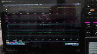
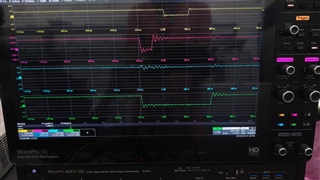
    For chip selects 2 and 3( 0xA0000000,0xC0000000) is fine as expected, ALE is getting high and constantly low. (yellow signal is rd enable and pink is ALE)

    But for chip selects 0 and 1( 0x60000000,0x80000000), ALE is inverted(getting low when required and constantly high) (yellow signal is rd enable and pink is ALE)

    can you please help me get the right behavior

     Attaching the configuration code snippet for your reference


     MAP_EPIDividerCSSet(EPI0_BASE,3,10);//cpld

          MAP_EPIDividerCSSet(EPI0_BASE,1,10);//sram

           MAP_EPIDividerCSSet(EPI0_BASE,0,10);

           MAP_EPIDividerCSSet(EPI0_BASE,2,10);

           MAP_EPIModeSet(EPI0_BASE, EPI_MODE_HB16);


           EPIConfigHB16Set(EPI0_BASE,     EPI_HB16_MODE_ADMUX | // sets up data and address as separate, D[15:0].

                                          EPI_HB16_WRWAIT_1 |  //EPI_HB16_WRWAIT_1 write wait 4 EPI clocks

                                          EPI_HB16_RDWAIT_1 |  // read wait 4 EPI clocks

                                          EPI_HB16_CSCFG_ALE_QUAD_CS|

                                          EPI_HB16_CSBAUD|

                                          EPI_HB16_BSEL ,

                                           0);

                    EPIAddressMapSet(EPI0_BASE,

                                        EPI_ADDR_PER_SIZE_64KB |

                                       //  EPI_ADDR_PER_BASE_C  // set base to 0xC0000000

                                        EPI_ADDR_QUAD_MODE //maps CS0n to 0x60000000, CS1n to 0x80000000, CS2n to 0xA0000000, and CS3n to 0xC0000000

                                         );

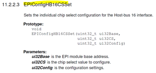
  • I don't see you configure each CS using EPIConfigHB16CSSet. 

  • Thanks Charles, it worked

    I see one other issue in the CS1 SRAM(IS62WV51216BLL-55TLI) and CS0 parallel flash(S29GL01GS) where in i'm not able to write/read addresses more than 128. It is getting stuck at the default handler.

    I'm not sure, but will this be because of BSEL configuration.

    Can you please tell where the issue could be.

  • Hello Charles

    This is similar to the previous issue where CS2 and CS3 are fine and other two chip selects having the issue of getting stuck in while(1) of default handler while accessing addresses more than 128.

    I also tried the same code with a launchpad which has no external devices connected, same is happening. 

    Is there something i'm missing in the configuration?

    MAP_SysCtlPeripheralEnable(SYSCTL_PERIPH_GPIOA);
              MAP_SysCtlPeripheralEnable(SYSCTL_PERIPH_GPIOB);
              MAP_SysCtlPeripheralEnable(SYSCTL_PERIPH_GPIOC);
              MAP_SysCtlPeripheralEnable(SYSCTL_PERIPH_GPIOG);
              MAP_SysCtlPeripheralEnable(SYSCTL_PERIPH_GPIOH);
              MAP_SysCtlPeripheralEnable(SYSCTL_PERIPH_GPIOK);
              MAP_SysCtlPeripheralEnable(SYSCTL_PERIPH_GPIOL);
              MAP_SysCtlPeripheralEnable(SYSCTL_PERIPH_GPIOM);
              MAP_SysCtlPeripheralEnable(SYSCTL_PERIPH_GPIOP);
              MAP_SysCtlPeripheralEnable(SYSCTL_PERIPH_GPIOQ);
              MAP_SysCtlPeripheralEnable(SYSCTL_PERIPH_GPION);


              MAP_GPIOPinConfigure(GPIO_PH0_EPI0S0);
              MAP_GPIOPinConfigure(GPIO_PH1_EPI0S1);
              MAP_GPIOPinConfigure(GPIO_PH2_EPI0S2);
              MAP_GPIOPinConfigure(GPIO_PH3_EPI0S3);
              MAP_GPIOPinConfigure(GPIO_PC7_EPI0S4);
              MAP_GPIOPinConfigure(GPIO_PC6_EPI0S5);
              MAP_GPIOPinConfigure(GPIO_PC5_EPI0S6);
              MAP_GPIOPinConfigure(GPIO_PC4_EPI0S7);
              MAP_GPIOPinConfigure(GPIO_PA6_EPI0S8);
              MAP_GPIOPinConfigure(GPIO_PA7_EPI0S9);
              MAP_GPIOPinConfigure(GPIO_PG1_EPI0S10);
              MAP_GPIOPinConfigure(GPIO_PG0_EPI0S11);
              MAP_GPIOPinConfigure(GPIO_PM3_EPI0S12);
              MAP_GPIOPinConfigure(GPIO_PM2_EPI0S13);
              MAP_GPIOPinConfigure(GPIO_PM1_EPI0S14);
              MAP_GPIOPinConfigure(GPIO_PM0_EPI0S15);
              MAP_GPIOPinConfigure(GPIO_PL0_EPI0S16);
              MAP_GPIOPinConfigure(GPIO_PL1_EPI0S17);
              MAP_GPIOPinConfigure(GPIO_PL2_EPI0S18);
              MAP_GPIOPinConfigure(GPIO_PL3_EPI0S19);
              MAP_GPIOPinConfigure(GPIO_PQ0_EPI0S20);
              MAP_GPIOPinConfigure(GPIO_PQ1_EPI0S21);
              MAP_GPIOPinConfigure(GPIO_PQ2_EPI0S22);
              MAP_GPIOPinConfigure(GPIO_PQ3_EPI0S23);
              MAP_GPIOPinConfigure(GPIO_PK7_EPI0S24);
              MAP_GPIOPinConfigure(GPIO_PK6_EPI0S25);
              MAP_GPIOPinConfigure(GPIO_PL4_EPI0S26);
              MAP_GPIOPinConfigure(GPIO_PB2_EPI0S27);
              MAP_GPIOPinConfigure(GPIO_PB3_EPI0S28);
              MAP_GPIOPinConfigure(GPIO_PN2_EPI0S29);
              MAP_GPIOPinConfigure(GPIO_PN3_EPI0S30);
              MAP_GPIOPinConfigure(GPIO_PK5_EPI0S31);
              MAP_GPIOPinConfigure(GPIO_PL5_EPI0S33);

              MAP_GPIOPinTypeEPI(GPIO_PORTA_BASE, (GPIO_PIN_7 | GPIO_PIN_6));
                        MAP_GPIOPinTypeEPI(GPIO_PORTB_BASE, (GPIO_PIN_2 | GPIO_PIN_3));
                        MAP_GPIOPinTypeEPI(GPIO_PORTC_BASE, (GPIO_PIN_7 | GPIO_PIN_6 | GPIO_PIN_5 |
                                                             GPIO_PIN_4));
                        MAP_GPIOPinTypeEPI(GPIO_PORTG_BASE, (GPIO_PIN_1 | GPIO_PIN_0));
                        MAP_GPIOPinTypeEPI(GPIO_PORTH_BASE, (GPIO_PIN_3 | GPIO_PIN_2 | GPIO_PIN_1 |
                                                             GPIO_PIN_0));
                        MAP_GPIOPinTypeEPI(GPIO_PORTK_BASE, (GPIO_PIN_5 |GPIO_PIN_6 |GPIO_PIN_7));
                        MAP_GPIOPinTypeEPI(GPIO_PORTL_BASE, (GPIO_PIN_5| GPIO_PIN_4 | GPIO_PIN_3 | GPIO_PIN_2 | GPIO_PIN_1 |
                                                             GPIO_PIN_0));
                        MAP_GPIOPinTypeEPI(GPIO_PORTM_BASE, (GPIO_PIN_3 | GPIO_PIN_2 | GPIO_PIN_1 |
                                                             GPIO_PIN_0));
                        MAP_GPIOPinTypeEPI(GPIO_PORTP_BASE, (GPIO_PIN_3 | GPIO_PIN_2));
                        MAP_GPIOPinTypeEPI(GPIO_PORTQ_BASE, (GPIO_PIN_3 | GPIO_PIN_2 |GPIO_PIN_1 |GPIO_PIN_0));

                        MAP_GPIOPinTypeEPI(GPIO_PORTN_BASE, (GPIO_PIN_3 | GPIO_PIN_2));
              /* Enable the clock to the EPI and wait for it to be ready*/
              MAP_SysCtlPeripheralEnable(SYSCTL_PERIPH_EPI0);
              while(!(MAP_SysCtlPeripheralReady(SYSCTL_PERIPH_EPI0)))
              {
              }


            MAP_EPIDividerCSSet(EPI0_BASE,3,10);//cpld
            MAP_EPIDividerCSSet(EPI0_BASE,1,58);//sram
            MAP_EPIDividerCSSet(EPI0_BASE,0,10);//parallel flash

            MAP_EPIModeSet(EPI0_BASE, EPI_MODE_HB16);
            EPIConfigHB16Set(EPI0_BASE,     EPI_HB16_MODE_ADMUX |
                                                  EPI_HB16_CSCFG_ALE_QUAD_CS|
                                                  EPI_HB16_CSBAUD|
                                                  EPI_HB16_BSEL ,
                                                  0);
            EPIConfigHB16CSSet(EPI0_BASE,1, EPI_HB16_WRWAIT_1 |   //EPI_HB16_WRWAIT_1 write wait 4 EPI clocks
                                            EPI_HB16_RDWAIT_1 |  // read wait 4 EPI clocks
                                            EPI_HB16_ALE_HIGH
                                            );
            EPIConfigHB16CSSet(EPI0_BASE,3,        EPI_HB16_WRWAIT_1 |   //EPI_HB16_WRWAIT_1 write wait 4 EPI clocks
                                                   EPI_HB16_RDWAIT_1 |  // read wait 4 EPI clocks
                                                   EPI_HB16_ALE_HIGH
                                                   );
            EPIConfigHB16CSSet(EPI0_BASE,0,               EPI_HB16_WRWAIT_1 |   //EPI_HB16_WRWAIT_1 write wait 4 EPI clocks
                                                          EPI_HB16_RDWAIT_1 |  // read wait 4 EPI clocks
                                                          EPI_HB16_ALE_HIGH
                                                          );

     EPIAddressMapSet(EPI0_BASE,
                                      EPI_ADDR_PER_SIZE_64KB |
                                          EPI_ADDR_QUAD_MODE //maps CS0n to 0x60000000, CS1n to 0x80000000, CS2n to 0xA0000000, and CS3n to 0xC0000000
                                          );

    Thanks in advance

  • Hi Monica,

      Sorry for the late reply as I was out of office and just got back. 

    This is similar to the previous issue where CS2 and CS3 are fine and other two chip selects having the issue of getting stuck in while(1) of default handler while accessing addresses more than 128.

    Can you be specific which default handler you are referring to? Are you referring to the IntDefaultHandler()? If yes, it means you did not provide a interrupt vector for EPI. 

    //*****************************************************************************
    //
    // This is the code that gets called when the processor receives an unexpected
    // interrupt. This simply enters an infinite loop, preserving the system state
    // for examination by a debugger.
    //
    //*****************************************************************************
    static void
    IntDefaultHandler(void)
    {
    //
    // Go into an infinite loop.
    //
    while(1)
    {
    }
    }

  • Hello Charles,

    The code got stuck in below default handler.

    /* This is the code that gets called when the processor receives an unexpected  */
    /* interrupt.  This simply enters an infinite loop, preserving the system state */
    /* for examination by a debugger.                                               */
    void Default_Handler(void)
    {
        /* Fault trap exempt from ULP advisor */
        #ifdef __TI_ARM__
            #pragma diag_push
            #pragma CHECK_ULP("-2.1")
        #endif

        /* Enter an infinite loop. */
        while(1)
        {
        }

        #ifdef __TI_ARM__
            #pragma diag_pop
        #endif
    }

    Actually the issue got resolved after adding this line of code  

    EPIAddressMapSet(EPI0_BASE,
                                      EPI_ADDR_PER_SIZE_64KB |EPI_ADDR_CODE_SIZE_16MB|EPI_ADDR_RAM_SIZE_256MB |
                                          EPI_ADDR_QUAD_MODE //maps CS0n to 0x60000000, CS1n to 0x80000000, CS2n to 0xA0000000, and CS3n to 0xC0000000
                                          );

    before i only added the below code and it worked for both CS2 and CS3

    EPIAddressMapSet(EPI0_BASE,
                                                   EPI_ADDR_PER_SIZE_64KB |
                                                   EPI_ADDR_QUAD_MODE //maps CS0n to 0x60000000, CS1n to 0x80000000, CS2n to 0xA0000000, and CS3n to 0xC0000000
                                                   );

    I'm trying to understand the reason behind. Can you please tell how it is working for CS2 and CS3 and not for other two?

  • Hi Monica,

      You need to use EPIAddressMapSet to specify the base address of a EPI memory as well as the size of the memory. In your oriignal code, you only specify the Peripheral Address Space Size and the base addresses of the four CS using EPI_ADDR_RAM_QUAD_MODE. However, you did not specify the Code Space Size. I suppose you are trying to run code out of EPI memory, right?

  • Hello Charles,

    Yeah Got it.

    I also had a look in TRM and its mentioned as below.

    If one of the Quad-Chip-Select modes is selected (CSCFGEXT is 0x1 and CSCFG is 0x2 or 0x3 in the
    EPIHBnCFG2 register), both the peripheral and the memory space must be enabled.

    External RAM Size This field selects the size of mapped RAM.
    If the size of the external memory is larger, a bus fault occurs.
    If the size of the external memory is smaller, it wraps (upper address
    bits unused):
    0x0 = 256 bytes; lower address range: 0x00 to 0xFF
    0x1 = 64 KB; lower address range: 0x0000 to 0xFFFF
    0x2 = 16 MB; lower address range: 0x000000 to 0xFFFFFF
    0x3 = 256 MB; lower address range: 0x0000000 to 0xFFFFFFF

    "If the size of the external memory is larger, a bus fault occurs" but how is the other two chip selects working if this is the issue. Even without any external devices connected to any CS, CS0 and CS1 hangs in the handler and CS2,CS3 doesn't stop anywhere.

  • "If the size of the external memory is larger, a bus fault occurs" but how is the other two chip selects working if this is the issue. Even without any external devices connected to any CS, CS0 and CS1 hangs in the handler and CS2,CS3 doesn't stop anywhere.

    Below comment is your prior description that you cannot read/write to addresses more than 128. With your original code the ERSZ register field is 0x0 meaning by default the size of mapped RAM is only 256 bytes. Since you are using a HB-16 then each access is two bytes. Any access beyond 256 bytes will create fault as explained in the datasheet. 

    I see one other issue in the CS1 SRAM(IS62WV51216BLL-55TLI) and CS0 parallel flash(S29GL01GS) where in i'm not able to write/read addresses more than 128. It is getting stuck at the default handler.
  • Hello Charles,

    Got it, Thank you..