This thread has been locked.

If you have a related question, please click the "Ask a related question" button in the top right corner. The newly created question will be automatically linked to this question.

LP-AM243: Regarding the MMC1 and μSD card usage

Part Number: LP-AM243
Other Parts Discussed in Thread: SYSCONFIG, TMDS243EVM

Tool/software:

I am having trouble with the MMC1 interface.
I have a small board that attaches to the launchpad with a μSD card connector.
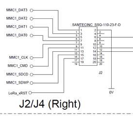
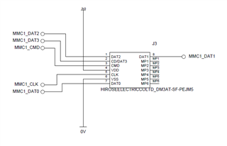
The connections are as shown in the below images.

The SD card connector is DM3AT-SF-PEJM5 from Hirose.
I have connected 4 DATA lines, 1 CLOCK line, 1 COMMAND line and 1 Chip Detect line between connector / LaunchPad.
The Chip Detect line is MP2 in the schematic, and I have it jumpered to GPIO1_77 (MMC1_SDCD = B17)
Power is taken from the header (3.3V / 0V)

Comparing to the AM243x-EVM schematics:
1) I don't have a PD resistor on the MMC1_CLK line
2) MMC1_SDWP = unused (no connection)

Are there any concerns on the HW setup?
What do I need to do SW-wise?
Is it enough to create an empty project for LP-AM243x, update SYSCFG for the MMC1 interface/connections,
then copy the main.c and mmcsd_raw_io.c into the project?

Do I have to make any changes for Write Protect, etc?
  • I also wanted to add, it seems like adding the MMC1 instance through SYSCFG causes the program to fail...I mean it builds fine, but when running on the LaunchPad - nothing.

    For example, take the standard Hello World example project (nortos, r5f).
    Build it and it runs fine, you get the "Hello World" text printed to serial terminal.

    But take the same Hello World example, and modify the SYSCFG to add MMCSD0 = MMC1, and yes the project builds, but now there is no activity / no text displayed...

    Can I get some advice on this?

  • I suggest you review the SD card connections on the AM64x EVM as an example of what you need to do with respect to connecting an SD Card to the MMC1 port of AM243x. I'm not able to answer any software questions. I will assign this thread to someone on the software team once we address your hardware questions.

    Regards,
    Paul

  • Hi Peaves,

    HW is the same as AM64x EVM.
    I had to jumper MMC1_CLK line with a 10kΩ resistor to GND, but now they are the same.
    Except for MMC1_SDWP - the write protect pin, which has no purpose on the LP-AM243x board.
    (The EVM connects this pin to some GPIO expander's xINT pin, and it looks like if Chip Detect isn't valid or something it triggers this interrupt)

    Before we jump into software, there is some behavior from SYSCFG I don't understand.
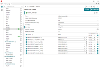
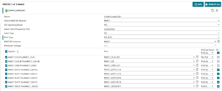
    I imported a stock Hello World example, and opened SYSCFG, adding the MMCSD interface with settings below.
    For some reason, setting "Card Type" parameter to eMMC or SD keeps the board from working (the project builds fine)
    But, when the "Card Type" parameter is set to "NO_DEVICE" then the board works and I get the "Hello World" message displayed.

    The only change is to SYSCFG - added the TI Drivers for MMCSD (MMC1) - but there is no SW actually using these drivers anywhere as the code is simply the imported Hello World example - no changes made. Yet why does the board freeze on boot if Card Detect is anything but NO_DEVICE?

  • You need to turn on the receiver associated with the CMD and CLKLB IO cells.

    The CMD signal is bidirectional, so the IO cell associated with this pin needs to have its receiver enabled.

    The pad associated with the CLKLB IO cell is not bonded to a device pin and it is used to loop a clock through the IO cell and back into the device such that the internal circuits operate from a delayed clock with similar delay that is introduced in the CLK output buffer plus the delay introduced in the DAT input buffers. This is done to help with read timing closure. The internal circuits will not have a clock unless you enable the receiver associated with the unbonded CLKLB IO cell.

    There is a note attached to the MMC1 Signal Descriptions table in the datasheet that tells you to keep the default state for the receiver enable associated with PADCONFIG164.

    Any pull-ups connected to MMC1 signals must be sourced from the VDDSHV5 power source that changes it operating voltage from 3.3V to 1.8V as the transfer speed increases. They should not be connected to a fixed 3.3V power source.

    Regards,
    Paul

  • I just realized the note attached to the MMC1 Signal Descriptions table should say:

    For MMC1 to work properly, the RXACTIVE and TX_DIS bits of the CTRLMMR_PADCONFIG164 register must remain in their default state because of retiming purposes.

    The original note did not mention the TX_DIS bit requirement.

    I would prefer to have CLKLB removed from the SYSCONFIG tool to avoid any chance of someone changing the default state of the RXACTIVE and TX_DIS bits of the CTRLMMR_PADCONFIG164 register, which is the PADCONFIG register associated with the unbounded MMC1_CLKLB IO cell.

    Then we would remove the note from the MMC1 Signal Descriptions table because these bits already default to the proper state. The note is only need now because the SYSCONFIG tool is providing a way for customers to accidently change them to an invalid state.

    Regards,
    Paul

  • There is something else I forgot to discuss.

    You need to implement a software-controlled load switch that is common to the SD Card power and the dual voltage power source required for VDDSHV5.

    I'm not familiar with board you are using, but it may not be easy to do what you need to do if the designer didn't make provisions for connecting an SD Card.

    You should look at how the VDDSHV5 and SD Card power sources are implemented on the AM64x EVM. A similar power solution is needed to support UHS-I SD Cards that dynamically change their IO operating voltage. You also need to provide a way to cycle power to the SD Card and VDDSHV5 power source at the same time when you need to reset the SD Card. This is needed because SD Cards do not have a reset pin. They can only be reset by cycling power. You must cycle power to the VDDSHV5 power source at the same time to prevent current injection into the SD Card non-fail-safe inputs when its power is cycled.

    Regards,
    Paul

  • Hi Paul,

    Since I am trying to get uSD working on LP-AM243x I am referencing the TMDS243EVM schematics from the design package. (Board design is basically shared with AM64x?)

    In the design I see the following.

    uSD power comes from a load switch sourced from just 3.3V, generated from LM5140. There is no 1.8V switching capability on the EVM.

    The load switch ENABLE pin comes from a GPIO expander controlled via I2C.

    When SYSCFG is setup to use MMC1, there is no pin defined for a load switch enable. Makes sense as it is controlled via I2C here.

    I understand this means the SW driver needs to handle load switch power cycling when resetting the card after things like formatting, etc.

    But in the MMCSD example program for the TMDS243EVM (mmcsd_raw_io) the first function call in SW related to MMCx is MMCSD_getBlockSize().

    Because of this, it looks like the load switch is enabled by default, and nowhere in the code is an I2C API used to toggle the ENABLE pin and power cycle the card.

    If this understanding is correct, the MMCSD examples dont control the load switch at all, correct? 

  • On the TMDS243EVM, the load switch is sourced by a 3.3V power supply, and the output of the load switch sources power to the SD Card and the SDIO_LDO (VDDA_3P3_SDIO) inside the AM243x device. The SDIO_LDO output (CAP_VDDSHV_MMC1) is connected to the dual-voltage power rail associated with the MMC1 IOs (VDDSHV5) and the pullup resistors connected to the MMC1 signals. This way the IOs of both devices will be turned off when the load switch turns off. The load switch is controlled by three signals. The PORz_OUT which resets the AM243x device, the AM243x RESETSTATz output, and a GPIO that defaults to an off state. The pull-up on the GPIO will allow the load switch to turn on by default as soon as the AM243x completes its reset process. At some time later, software can configure the GPIO and drive the signal low to reset the SD Card if necessary.

    The output of the SDIO_LDO will initially be 3.3V and change to 1.8V after one of the faster data transfer modes has been selected. The MMC1 host controller will change the SDIO_LDO voltage at the same time it sends a command to the SD Card telling it to change voltage.

    The TMDS243EVM should have been built with 47K pull-ups installed on the CMD and DAT signals and a 47k pull-down installed on CLK. The external pull resistors are required to hold the SD Card input in a valid logic state until software initializes the AM243x pins since the AM343x pins are off by default.

    The LP-AM243x does not implement a 3.3V load switch for the power supply sourcing SDIO_LDO or the connector that contains the MMC1 signals, so there is no way for you to cycle power to the SDIO_LDO and SD Card connected via the connector. It appears LP-AM243x was not designed to support an SD Card. I suspect it was only designed to support an embedded SDIO device like a Wi-Fi radio.

    Regards,
    Paul

  • Hi Paul,

    The LP-AM243x does not implement a 3.3V load switch for the power supply sourcing SDIO_LDO or the connector that contains the MMC1 signals,

    I understood on the TMDS243EVM design, the SD Card Load Switch enable signal comes from a GPIO expander controlled via the I2C1 interface.
    The same I2C1 interface is available through the LaunchPad headers, so technically it is possible to replicate the setup on the LaunchPad...except that pressing the push-button for SOC reset won't power cycle the SD card - you would have to completely remove power to the board in that case.
    (my understanding)

    Right now, I think jumping into SW will provide more clarity on what is causing the MMCSD driver to hang.

    With my MMCSD SYSCFG settings as shown in the image above (a few posts back), I have narrowed down my issue.

    1) The main application *.c file calls Drivers_open(); which does the following (based on SYSCFG configuration):

    void Drivers_open(void)
    {
        Drivers_mmcsdOpen();
        Drivers_uartOpen();
    }

    2) In the Drivers_mmcsdOpen(); function, there is a call to MMCSD_open(); (found in "mmcsd_v0.c" in the PDK/source/drivers/mmcsd/v0 folder)

    3) Since SYSCFG is setup with Card TypeSD, this function calls MMCSD_initSD();

    4) The MMCSD_initSD(); function calls MMCSD_phyInit(); which is where the driver gets stuck in an infinite loop.
    5) The below code in phyInit(); is where I see the program hanging.
    while(CSL_REG32_FEXT(&ssReg->PHY_CTRL_1_REG, MMC_SSCFG_PHY_CTRL_1_REG_EN_RTRIM) != 1U);

    if(phyType == MMCSD_PHY_TYPE_HW_PHY)
        {
            /* Set DLL_TRIM_ICP value to 8 */
            CSL_REG32_FINS(&ssReg->PHY_CTRL_1_REG, MMC_SSCFG_PHY_CTRL_1_REG_DLL_TRM_ICP, 8U);
    
            /* Reset PHY CONTROL 2 REG */
            CSL_REG32_WR(&ssReg->PHY_CTRL_2_REG, 0U);
    
            /* Reset PHY CONTROL 3 REG */
            CSL_REG32_WR(&ssReg->PHY_CTRL_3_REG, 0x10FF10FF);
    
            /* Do the calibration */
            /* Set EN_RTRIM bit */
            CSL_REG32_FINS(&ssReg->PHY_CTRL_1_REG, MMC_SSCFG_PHY_CTRL_1_REG_EN_RTRIM, 1U);
            while(CSL_REG32_FEXT(&ssReg->PHY_CTRL_1_REG, MMC_SSCFG_PHY_CTRL_1_REG_EN_RTRIM) != 1U);
    
            /* Set PDB to trigger calibration */
            CSL_REG32_FINS(&ssReg->PHY_CTRL_1_REG, MMC_SSCFG_PHY_CTRL_1_REG_PDB, 1U);
    
            /* Wait for calibration to finish */
            while(CSL_REG32_FEXT(&ssReg->PHY_STAT_1_REG, MMC_SSCFG_PHY_STAT_1_REG_CALDONE) != 1U);
        }
    It looks to me like this code is trying to work with MMCSD0, instead of MMCSD1.
    I assume so, as there is no register field "EN_RTRIM" in MMCSD1 CTRL_1_REG.
    Also, the PHY_CTRL_2_REG are not available in MMCSD1.
    (Table 12-3775. MMCSD1 Subsystem Registers)
    I think the question is, why SYSCFG is calling up the MMCSD0? initialization when SYSCFG is clearly set to use MMCSD1...?
  • Hi Paul,

    I know I just posted but...I was able to get it to work.
    By changing the SYSCFG parameter for PHY Type = NO_PHY I was able to get everything to run.
    (Just preliminary test, not perfect as with no load switch there is no way to reset after CRC error, etc)

    Can you confirm for me what this setting does, and why MMCSD1 needs "NO_PHY" to work on the LP-AM243x?

  • There is no way to switch the input to the SDIO_LDO on the LP-AM243x, and it must be powered from the same load switch that controls power to the SD Card. It is very important that you implement the proper power solution, where the same load switch cycles power to the CD Card and the SDIO_LDO. You could damage the devices if you do not do this. I do not see an easy way for you to be able to implement the proper SD Card power solution on LP-AM243x.

    As mentioned before, I do not provide any software support. I will need to assign this thread to someone on the software team if you are done with hardware questions. Are you ready for me to reassign the thread?  If so, what software package are you using?

    Regards,
    Paul

  • Hi Paul,

    When we design our board I will make sure we implement the load switch as you have described.
    For now, since I have communication and verified R/W data to card, I believe I am comfortable with hardware on the LaunchPad.

    For software, I guess at this point I want to understand what the "PHY Type" parameter in SYSCFG does, and what the difference is between the three settings.

    Thanks!

  • We do not need to assign this question to the software team.

    I will discuss this topic with our SYSCONFIG tool expert and see if they are able to confirm what I think it means.

    We have two IO implementations for MMC ports. One implementation is an actual eMMC/SDIO PHY that has dedicated signal functions for each pin and only supports 1.8V IO signaling. The MMC0 port on AM243x uses the eMMCPHY buffer type, which is an example of that implementation. The other implementation uses a slightly modified LVCMOS IO cell for each pin and they support multiplexing of other signal functions and 1.8V or 3.3V IO signaling. The MMC1 port on AM243x uses the SDIO buffer type, which is an example of that implementation.

    The buffer type implemented for each pin can be found in the Pin Attributes table and each buffer type has its own Electrical Characteristics section in the datasheet.

    I suspect the NO_PHY option should be selected for MMC1 since it uses the SDIO buffer type rather than the eMMCPHY buffer type. I will try to confirm that is the case and let you know tomorrow.

    Regards,
    Paul

  • I finally got an answer about the NO_PHY option from the SYSCONFIG team, but it didn't make sense. Now I need to discuss the answer they provided with the MMCSD software driver team to get a better explanation.

    Regards,
    Paul

  • I finally got resolution from the software team. The NO_PHY selection doesn't have any impact on how software configures the hardware.

    The software team has filed an internal request to remove the NO_PHY selection from the AM243x SYSCONFIG tool. This should eliminate any confusion associated with its purpose.

    Regards,
    Paul