This thread has been locked.

If you have a related question, please click the "Ask a related question" button in the top right corner. The newly created question will be automatically linked to this question.

LP-AM243: SDDF cycle time(ICSSG0-PRU0) affects BissC cycle time(ICSSG0-PRU1)

Part Number: LP-AM243
Other Parts Discussed in Thread: AM2431

Tool/software:

Hi, I am trying to modify from single_chip_servo_am243x-lp_r5ss0-0_nortos_ti-arm-clang to build a demo which can be run on AM2431.

USE_OPEN_LOOP_WITH_SDDF is defined to run open loop with sddf.

I changed the encoder from ENDAT to BissC (Code is based on BissC single channel diagnostic) using ICSSG0_PRU1.

Baudrate is 2Mhz. Core clk and IEP clk is 200Mhz.
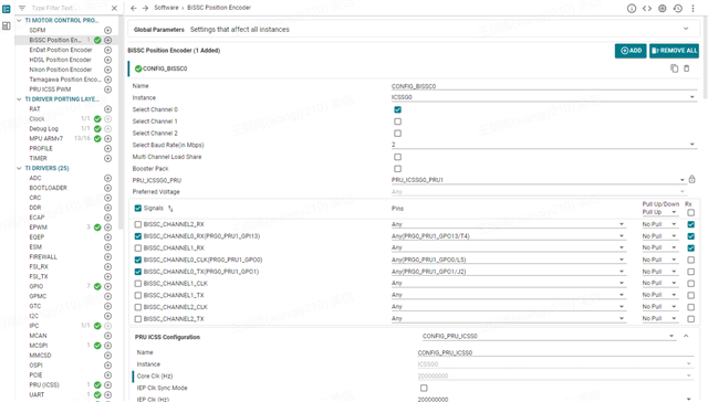
IEP clock in Struct SdfmPrms gTestSdfmPrms is also changed to 200Mhz.

Configured position cycle is 16Khz.

The issue is,

1. The cyclic position is 16Khz if APP_EPWM_OUTPUT_FREQ defined in pwm.h is 4K or 8K.

2. There is no output in clock and data if  APP_EPWM_OUTPUT_FREQ is 20k or 50k.

3. The cycle time is around 310 us if APP_EPWM_OUTPUT_FREQ is 16k.

In all 3 test cases, the motor would rotate normally. Position data is available in case 1 and 3, not in case 2.

My question is whether the SDDF and BissC can work in 16Khz with ICSSG0 since ICSSG1 should be used for EtherCAT.

Thanks.

So my goal is to 

  • Hi Jainyu,

    Thanks for your query.

    I will check on this and get back to you.

    Can you also share the code where you have made changes?  

    Best Regards

    Achala Ram

  • I added file bissc_periodic_trigger.c and bissc_periodic_trigger.h, and relative libs and includes.

    Added file BissCHandle.c, BissCHandle.h

    File Single_chip_servo.c mainly changed Function single_chip_servo_remote_core_start() and removed ENDAT related function.

    Added and modified files.zip

  • I checked again with the code. This project can be run with a rotary motor with 17-bit BissC encoder. Changing APP_EPWM_OUTPUT_FREQ would affect both PWM frequency and the data request frequency of the encoder.

    single_chip_servo_am243x-lp_r5fss0-0_nortos_ti-arm-clang.zip

  • Hi Jianyu,

    In code I saw that CMP0 & EMPW sync out both events are used to reset IEP, so you need to change CMP0 value also to sync EPWM cycle & position cycle.

    I think you are not changing feedback capture cycle time according to EPWM cycle time, so you are not getting correct cycle time.

    To get desired cycle time you have to always define CMP0 value equal to EPWM cycle time*IEP clock value time 

    The cyclic position is 16Khz if APP_EPWM_OUTPUT_FREQ defined in pwm.h is 4K or 8K.

    In your code defined cmp0 (12500 (62.5us @16KHz ) )value is for 16KHz EPWM cycle so cycle time is always 16Khz. 

    Can you define CMP0 value equal to EPWM cycle time & try ? 

    Thanks & Regards

    Achala Ram 

  • Hi Achala,

    I did not follow you.

    The equation should be 1/APP_EPWM_OUTPUT_FREQ(16k) * IEP_CLK(200Mhz) = 200,000,000 / 16,000 = 12500.

    And the feedback cycle time is correct if APP_EPWM_OUTPUT_FREQ is set to 8K or 4K. 

    I have updated CMP3 and CMP0 as your suggestion. When APP_EPWM_OUTPUT_FREQ = 16K, the result is still incorrect.

    Another issues though, I am not sure if related.

    First, in the origin encoder, CMP0 and CMP3 is set as 3000. The cycle time should be 10 us as IEP clock is 300Mhz.

    Secondly, I compared endat_periodic_trigger.c in single_chip_servo_am243x-lp_r5ss0-0_nortos_ti-arm-clang and the same file in endat_diagnostic_single_channel_am243x-lp_r5ss0-0_freertos_ti-arm-clang. CMP0 is doubled. I am not sure about the purpose of the difference and wonder if that is related to my issue.


  • in the origin encoder, CMP0 and CMP3 is set as 3000. The cycle time should be 10 us as IEP clock is 300Mhz.

    No, that is 20us for 50KHz EPWM cycle. In EnDAT Encoder CMP3 is used to trigger position feedback at middle of EPWM cycle & CMP0 is used to reset IEP at end of EPWM cycle.

    You can see in original code as 3000 (10us exact middle of EPWM cycle @50KHz) is used for position feedback point and 2*3000(20us end of EPWM cycle @50KHz) is used for IEP reset point.

  • I have updated CMP3 and CMP0 as your suggestion. When APP_EPWM_OUTPUT_FREQ = 16K, the result is still incorrec

    Can you share more details on this? how much difference are you seeing in cycle timing?

  • Very interesting though. I wrote the code according to cmp0 and cmp3 are both 3k, which in reality is that cmp0 is 6000 and cmp3 is 3000.

    Now I do the following change, and the BissC cycle time is now correct.

    So do you have any suggestion on the value selection of cmp3? I have also tried cmp3 =  cmp0/2 but then there is no data and clock from the pin. It feels like cmp3 has a minimum, which would stop the output when too small, and a maximum,  which should be lower and not equal to cmp0.

  • So do you have any suggestion on the value selection of cmp3? I have also tried cmp3 =  cmp0/2 but then there is no data and clock from the pin.

    You can configure between '0' and configured value of cmp0, as I mentioned that IEP is getting two reset events at the same time (one internal from CMP0 & one external from EPWM sync out ) that can cause a problem for edge cases I mean cmp3=0 and cmp3=cmp0, except these two values of CMP3 It should work correctly. Let me review the code again for the cmp3 = cmp0 / 2 configuration, Original code is working for this case where cmp3 = 3000 and cmp0 = 6000 ( cmp3 = cmp0 / 2 )

    I have also tried cmp3 =  cmp0/2 but then there is no data and clock from the pin

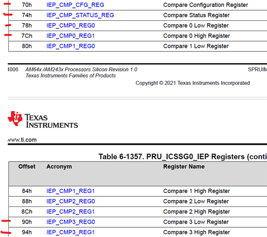
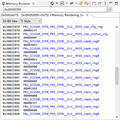
    This means that the IEP CMP3 is not getting hit and the firmware is not starting communication to the encoder, As the firmware is waiting for the CMP3 event to be hit, can you check the IEP registers? check CMP3 register value and IEP CMP status register values?

    Thanks & Regards,

    Achala Ram

  • This means that the IEP CMP3 is not getting hit and the firmware is not starting communication to the encoder, As the firmware is waiting for the CMP3 event to be hit, can you check the IEP registers? check CMP3 register value and IEP CMP status register values?

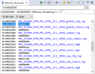
    Currently I use 16Khz, so cmp3 is 6250 and cm0 is 12500. IEP CMP status stucks in 1.

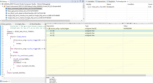
    And in the code, the bissc position function stucks in function bissc_command_wait(), the cycle_trigger[0] stucks in 1.

    I have tried a few values today, and it turns out that if cmp3 is smaller than 8500, the encoder returns nothing.

    There is also some issues I am wondering.

    1. cmp3 and sync delay

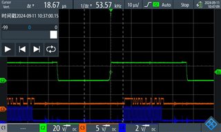
    This picture is the scope, green is phase U, orange is data - of the encoder, and blue is clk -. The cmp3 value is 8500. The dela time is measured between the middle point when U is low and the start point of clk -. Delta time is 18.67 us, and would increase to 24.93us when cmp3 is 11500.

    I can see that PWM and encoder time is synced. But I can't get how to calculate the difference time, increase cmp3 by 3000 should result in 15 us, right?

    2. feedback function implementation.

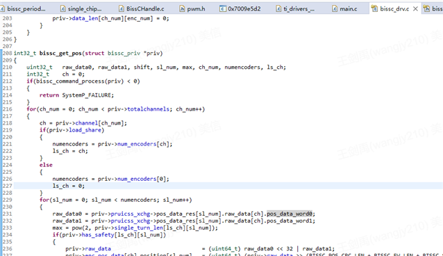
    I checked the function bissc_get_pos() in file bissc_drv.c, 

    In bissc_command_process, it includes 2 steps:

    - set pruicss_xchg->cycle_trigger[ch] = 1

    - wait until pruicss_xchg->cycle_trigger[ch] = 0.

    So I guess this step is mandatory to update the bissc feedback in priv->pruicss_xchg->pos_data_res[sl_num].raw_data?

    But the while loop is not good to put in the pwm_isr handler, and the origin endat code, there is no while loop, too.

  • Currently I use 16Khz, so cmp3 is 6250 and cm0 is 12500. IEP CMP status stucks in 1.

    You need to check marked CMP registers. 

  • CMP3 status bit is set so at least one time communication should happen, are you not seeing any communication over data & clock lines for CMP3 value 6250?

  • Hi Jainyu,

    increase cmp3 by 3000 should result in 15 us, right?

    Yes, correct as IEP is running @200MHz. 

    I have few questions

    What results are you seeing with 4k & 8K EPWM freq. ? is this working for CMP3=CMP0/2 case ?

    Just for clarification, Can you please share all cases where it is working & not working ? Please also share issues those you are seeing in not working cases.

    Working Case:

    Not working Case:

    Thanks & regards,

    Achala Ram

  • Working case:

    4k, 8k EPWM freq that cmp3 = cmp0/2. 16 k EPWM freq, cmp3 >= 8500

    Not working case:

    16 k EPWM freq, cmp3 < 8500

  • Thanks for sharing this!

    I will test & debug this not working case and get back to you.

    Meanwhile, you can check whether the IEP is being reset properly

    BR,

    Achala Ram

  • 16 k EPWM freq, cmp3 < 8500

    This is working for original code, I made two changes in code to use 16Khz

    • APP_EPWM_OUTPUT_FREQ = 16000
    • endat_periodic_interface.cmp3 = 300000000/(2*APP_EPWM_OUTPUT_FREQ)

    So can you check below mentioned things.

    1. Is IEP counter getting reset or not ?
    2. Halt the PRU core & check where it is stuck ? 
    3. If the IEP CMP3 status bit is set, then encoder communication must occur at least once

    Thanks & regards,

    Achala Ram