This thread has been locked.

If you have a related question, please click the "Ask a related question" button in the top right corner. The newly created question will be automatically linked to this question.

MSP432E401Y: CAN not working

Part Number: MSP432E401Y
Other Parts Discussed in Thread: MSP-EXP432E401Y

Tool/software:

Hello Team

We have a custom board with MSP432E401Y and a CAN transceiver TCAN1051HGVDR connected to both CAN0 and CAN1. With two of our custom board, we connected the CAN lines with a jumper wire, I tried to use the can_singlemessage_transmit_MSP_EXP432E401Y_nortos_ccs and can_single_message_receive_MSP_EXP432E401Y_nortos_ccs without changing anything from SDK which is implemented with CAN0.

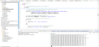
Please view the below image for output


I also tried to probe the CANTX and CANRX lines but no signals captured. 

And then modified and tested with CAN1 as well, but same behavior.

Can you please help in finding the issue..

Thanks in advance.

  • I also tried to probe the CANTX and CANRX lines but no signals captured. 

    Hi,

      Do you have proper termination resistor on the CAN bus? Refer to this app note. https://www.ti.com/document-viewer/lit/html/SSZTB40

      Can you show the scope waveform of the CANTX pin?

      Do you have a MSP-EXP432E01Y board? Although the launchPad has no CAN transceiver on it, but if you run the example, it should at least show the digital side of the CANTX waveform. Please refer to the LaunchPad user's guide for details. 

    2.1.6.2 BoosterPack Plug-in Module Interface 2 The second BoosterPack XL interface is located near the bottom of the board. This interface is fully compliant with the BoosterPack plug-in module standard, and adds features not covered by the BoosterPack plug-in module standard that enable operation with additional BoosterPack plug-in modules. Using the jumpers JP4 and JP5, Controller Area Network (CAN) digital receive and transmit signals can be optionally routed to the BoosterPack Plug-in Module Interface 2 connector. In the default configuration, UART0 is used for the XDS-110 backchannel UART and CAN is not present on the BoosterPack plug-in module headers. In this configuration, the ROM serial bootloader can be used over the XDS-110 backchannel UART. When the jumpers are configured for CAN on the BoosterPack plug-in module interface, then UART2 must be used for the XDS-110 backchannel UART.

  • Charles Tsai said:

    Do you have proper termination resistor on the CAN bus?

    Yes, terminations are fine.

    The signal is not even coming out of CANTx line. 


    With the code from TI resource explorer in MSP-EXP432E401Y,we tried probing the PA1 from the booster-pack with the above mentioned connections. The PA1 signal is always high and UART printing is as below


  • Hi,

      Did you change JP4 and JP5 to their horizontal positions? Refer to the LaunchPad user's guide for details. 

    JP2 separates the MCU 3.3-V power domain from the rest of the 3.3-V power on the board allowing an
    ammeter to be used to obtain more accurate measurements of microcontroller power consumption. JP4
    and JP5 are used to configure CAN signals to the BoosterPack Plug-in Module Interface 2 connector. In
    the default vertical configuration, CAN is not present on the BoosterPack plug-in module connector.
    UART2 goes to the BoosterPack plug-in module connector and UART 0 goes to the XDS-110
    backchannel serial port and can also be used for the ROM serial bootloader. In the horizontal CAN enabled
    configuration, UART2 goes to the XDS-110 backchannel serial port and CAN signals are
    available on the BoosterPack Plug-in Module Interface 2 connector. The ROM serial bootloader is not
    available to the XDS-110 backchannel serial port while the jumpers are in the CAN position.
    Figure 3 shows the default configuration and relative location of the jumpers on the board.

  • Yes, jumpers are in horizontal position as mentioned above. UART2 is used. We also modified the same code for CAN1, that is also showing high always in CANTX. no data transfer seen.


  • I think you need to form a real network with at least two nodes on the bus. I don't think it will work with only one node. The LaunchPad does not have a transceiver but you can use diode to simulate a transceiver when nodes are short distance from each other. See below article. I've tried using diode in the past and it works. Again, you must have two nodes on the network. 

    https://electronics.stackexchange.com/questions/383603/can-bus-on-pcb-board/383609

  • Hello Charles,
    Thank you for your reply.

    We have connected a CAN transceiver (TCAN1051HGVDR) to the launch pad.
    The transceiver is on one of our custom board.
    The pins are PA1 - CAN0Tx and PA0 - CAN0Rx.
    At the other end of the CAN line, we have made a similar setup.
    The issue we are seeing now is, the signals are not even coming out of the CAN0Tx pin of the MSP432 controller when it is configured as CAN.
    We checked by configuring the PA0 pin as GPIO pin just to check whether there is any issues with the soldering of the pin, but it was working properly.
    The issue happens only when the PA0 and PA1 are configured as CAN.


  • Hi,

      Can you take a picture of the LaunchPad board for the JP4/JP5 orientation?

  • Did you press SW1 in order for the CAN controller to send the message if you were running the can_singlemessage_transmit_MSP_EXP432E401Y_nortos_ccs example?

  • Hello Charles,

    This is how we connected the JP4 and JP5.
    Instead of taking the CAN Tx and CAN Rx pin from the booster pack, we have directly taken from the JP4 and JP5 directly.
    We connected the JP4 and JP5 in the following manner as well and took the CAN Tx and RX signals out of the booster pack.

    But the results are still the same.

  • Hi,

      In the below CAN app note there is a simple_tx example. Although this is an example for TM4C129 MCU, you should be able to load the firmware and run as-is for MSP432E because TM4C129 and MSP432E are the same silicon. You still need to have the correct jumper settings on your LaunchPad. 

    Using the Edde Flex CAN Controller on the EK-TM4C1294XL LaunchPad

  • For TM4C micro controller, the CAN lines are in PE4 and PE5 where in MSP432 its in PA0 and PA1. Even if I flash this code and keep the jumper properly I wont be able to see any output right? Please correct me if I'm wrong.          

     Or do you want me to check PE4 and PE5 pins for CAN signals?


  • For TM4C micro controller, the CAN lines are in PE4 and PE5 where in MSP432 its in PA0 and PA1. Even if I flash this code and keep the jumper properly I wont be able to see any output right? Please correct me if I'm wrong.          

    That is not true. TM4C has the same pinout as MSP432E. For CAN0, the RX and TX pins are on PA0 and PA1 just like MSP432E. See the below snippet of code in the TM4C129 simple_tx.c file. 

    //
    // For this example CAN0 is used with RX and TX pins on port A0 and A1.
    // The actual port and pins used may be different on your part, consult
    // the data sheet for more information.
    // GPIO port A needs to be enabled so these pins can be used.
    // TODO: change this to whichever GPIO port you are using
    //
    MAP_SysCtlPeripheralEnable(SYSCTL_PERIPH_GPIOA);

    //
    // Configure the GPIO pin muxing to select CAN0 functions for these pins.
    // This step selects which alternate function is available for these pins.
    // This is necessary if your part supports GPIO pin function muxing.
    // Consult the data sheet to see which functions are allocated per pin.
    // TODO: change this to select the port/pin you are using
    //
    MAP_GPIOPinConfigure(GPIO_PA0_CAN0RX);
    MAP_GPIOPinConfigure(GPIO_PA1_CAN0TX);

    //
    // Enable the alternate function on the GPIO pins. The above step selects
    // which alternate function is available. This step actually enables the
    // alternate function instead of GPIO for these pins.
    // TODO: change this to match the port/pin you are using
    //
    MAP_GPIOPinTypeCAN(GPIO_PORTA_BASE, GPIO_PIN_0 | GPIO_PIN_1);

    //
    // The GPIO port and pins have been set up for CAN. The CAN peripheral
    // must be enabled.
    //
    MAP_SysCtlPeripheralEnable(SYSCTL_PERIPH_CAN0);

    Below is the TM4C129 CAN signal table.