This thread has been locked.

If you have a related question, please click the "Ask a related question" button in the top right corner. The newly created question will be automatically linked to this question.

TMS570LS1224: MibSpi3 register RxBuf read value of 0, which is not consistent with SPI log (0x0688)

Part Number: TMS570LS1224
Other Parts Discussed in Thread: TPS65381A-Q1

Tool/software:

Dear Madam/Sir,

I am encountering MibSpi3 RxBuf value not consistent with the SPI log.

My situation is: the SPI3 is shared between TI TPS65381A-Q1 (psu) and Microchip MCP3208 (adc), and we implemented semaphore for the exclusive access. Previously we read adc value from MCP3208 (on SPI3), and every thing is ok and we got the correct read, and SPI3 RxBuf is correct.

Recently in our project, I enabled the TPS65381A DMUX, in order to measure the DIAG_OUT, which is connected to one of TMS chip adc input. After that, we always get SPI RxBuf value of 0, but from the log, we can see the communication is correct and the value transferred is correct, see attachment. If we remove the DMUX in our project, then everything works fine again.

By the way, TPS65381A AMUX always works, no issue at all. Only the DMUX will this issue.

It's very strange, could you help me to understand and debug the issue? Thank you very much.

  • Hi ,

    I want to know the following things:

    1. Are you using different chip selects for both the slaves (TPS65381A and MCP3208) or else you are using the same chip select?

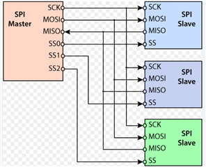
    2. Usually, SPI master with multiple slaves should be like below:

    But what is the connectivity at your end?

    3. How you are enabling and selecting required channel on DIAG_OUT? is it through SPI communication only right?

    Recently in our project, I enabled the TPS65381A DMUX, in order to measure the DIAG_OUT, which is connected to one of TMS chip adc input.

    --

    Thanks & regards,
    Jagadish.

  • Hi Jagadish,

    Thank you for looking into my issue. To clarify:

    1. Yes, we are using different chip selection pin for both slaves, as the log shows: HVM_CS is for MCP3208, and TPS_CS is for TPS65381A.

    2. Yeah, understand, in our case, we only have two slaves. Both CS are connected to different TMS pins (MIBSPI3NCS[0] and MIBSPI3NCS[1]).

    3. Yes, to enable TPS65381A DMUX, we are using SPI communication only.

    We have TPS65381A AMUX enabled through SPI without an issue, the SPI RxBuf works with correct value. Only after we enable DMUX through SPI, we get this issue.

    Scenario1: with DMUX enabled only, the SPI RxBuf always get 0 (reading mcp chip).

    Scenario2: with AMUX and DMUX switched every 50ms. When AMUX is enabled, SPI works fine, at next 50ms DMUX enabled (AMUX disabled), SPI RxBuf is 0 (reading mcp chip), but at the same time, the SPI log shows SPI is transferirng the correct value.

    Looks the SPI RxBuf doesn't match with spi log transmission.

    Don't know if it's clear enough, if need more information, just let me know. Thanks you very much.

    Best regards

    Longhua

  • Hi Longhua,

    There should not be much difference between AMUX and DMUX right?

    I am working on this slave device for the first time, so correct me if i am wrong:

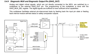
    So, using this DIAG_OUT pin we can monitor either digital signals or analog signals in the TPS65381A right? This DIAG_OUT signal should need to connect to the controller.

    Now which signals should need to pass to the controller will be decided by DIAG_MUX_SEL register, if i am now wrong?

    If this is correct, then:

    As SPI communication and these DIAG_OUT signals are completely different, choosing DMUX should not have any effect on SPI communication, right? But you are saying this is happening, if this is the case then the only possibility is that GND or VCC are affecting, my suspecting

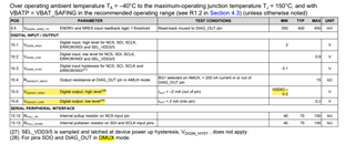
    Because as you can see if DMUX selected the voltage levels are based on VCCIO and corresponding GND.

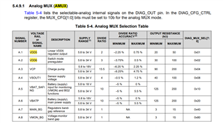
    But if AMUX selected then the voltage levels are different, and they are based on other supply GND (may be).

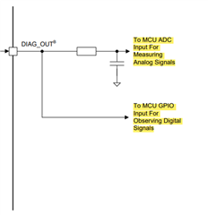
    Did you connect the DIAG to the two pins (One analog pin for AMUX signals and one digital pin for DMUX signals) of controller like as shown below?

    Can i get complete connectivity diagram for verification? Even you can send it through private chat as well. Because i want to verify how you are handling the GND's?

    --
    Thanks & regards,
    Jagadish.

  • Hi Jagadish,

    Thanks for your quick response. Yes, you're right, DMUX or AMUX doesn't have relationship with SPI3. The only difference is that the DIAG_OUT is analogue or digital out depends on the selection.

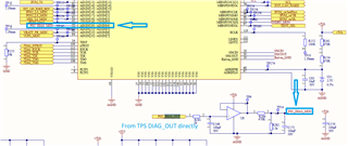
    Unfortunately, because short of GPIO in our project, the DIAG_OUT is connected to one ADC input (AD1IN[20]) only. In this case we're trying to measure the digital input through the same ADC input when DMUX is selected.

    I am also suspecting this solution could cause the issue. Please see the connection of DIAG_OUT. To see if anything wrong? Thanks.

    Best regards

    Longhua

  • Hi Longhua,

    Is it possible to share the connectivity of TPS65381?

    --
    Thanks & regards,
    Jagadish.

  • Hi Jagadish,

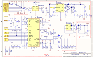
    Yes, sure, the schematic is as following. Will you need anything more, just let me know. Thanks.

    Best regards

    Longhua

  • Hi Longhua,

    I think your ground connections fine, i mean even through analog pin cannot sample the VCCIO levels of digital signals form TPS65381, they won't create any issue on the SPI communication.

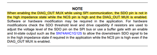
    However, i found below note in the datasheet of TPS65381:

    According to it "When enabling the DIAG_OUT MUX while using SPI communication, the SDO pin is not in the high impedance state while the NCS pin is high, and the DIAG_OUT MUX is enabled.".

    Actually, SDO pin should be at high impedance state if the NCS of TPS35381 is high but what this note is saying that even though NCS is high if DIAG_OUT MUX enabled then ASO pin will not be in high impedance state.

    For example, refer below diagram:

    I think our connectivity is as per above diagram only right, see the SDO pins of both slaves will be shorted and connected with SDI of the controller, right? So that means if the NCS (or SS) pin high then as per the note they are saying SDO will not be in high state, that means it driving some signals, what if that voltage is logic-0? it will affect the other slave communication, right?

    May be this is the problem we are seeing when DMUX enabled.

    --
    Thanks & regards,
    Jagadish.

  • Hi Jagadish,

    Thanks for your point, that's a great finding, really helpful. I will check with the hardware team to review the note if something missed or can be done.

    Anyway, if that's the problem, why AMUX doesn't cause the issue, as the note just saying enabling DIAG_OUT MUX, it includes AMUX and DMUX as well. The issue only happens when DMUX is enabled.

    By the way, the TPS SDO is connected to TMS570 MISO directly, no resistor between. The MCP does have a resistor between, as following:

    For hardware: do you suggest a similar resistor can be added between TPS SDO and TMS570 MISO?

    For software: I can't think out a solution, as AMUX works in this scenario. What I can think out is, do not reading the mcp through SPI when DMUX is enabled (duration of 50ms), as the SPI is not working properly at that time.

    Could you help to investigate further? Thank you very much.

    Best regards

    Longhua

  • Hi Longhua,

    Anyway, if that's the problem, why AMUX doesn't cause the issue, as the note just saying enabling DIAG_OUT MUX, it includes AMUX and DMUX as well. The issue only happens when DMUX is enabled.

    You are correct we should also receive for AMUX as well, not sure why it is not occurring for AMUX.

    For hardware: do you suggest a similar resistor can be added between TPS SDO and TMS570 MISO?

    Usually, i never saw serial resistors on SPI lines. I don't know how this will helpful, so i can't recommend anything related to it.

    --
    Thanks & regards,
    Jagadish.

  • Hi Jagadish,

    Sorry for late response. I think you are right. I have tried to tap the SDO pin from the MCP3028 as following: point 1 and point 2 when DMUX enabled only. (as there is a resistor between MCP3208 and TMS570)

    At point 1: The SPI log shows the MISO data are correct.

    At point 2: The SPI log shows the MISO data are always 0.

    Looks the MISO data are holding 0 by TPS65381 when DMUX are enabled.

    The only weird thing is why AMUX enabled doesn't cause this issue. Looks this issue is caused by TPS chip.

    Best regards

    Longhua

  • Hi Longhua

    The only weird thing is why AMUX enabled doesn't cause this issue. Looks this issue is caused by TPS chip.

    You are correct that was confusing to me as well.

    My suggestion would be better to raise another e2e thread related to the TPS65381A-Q1 part. If we do that then thread might be allocated to corresponding BU, who were expert on TPS65381A-Q1 part. So, they might answer better for this issue.

    --
    Thanks & regards,
    Jagadish.

  • Hi Jagadish,

    Sure, thanks for your help to investigate this issue to details. It's very helpful. We can close this thread now.

    Thanks

    Best regards

    Longhua