This thread has been locked.

If you have a related question, please click the "Ask a related question" button in the top right corner. The newly created question will be automatically linked to this question.

TM4C1231H6PM: Flash Program-Disable registers being set to 0 after first load of new rev. of software that's been working fine for 10 years.

Part Number: TM4C1231H6PM
Other Parts Discussed in Thread: SEGGER

Tool/software:

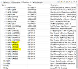
CCS  10.4.0.00006, when the latest version of our software is initially flashed, FMPRE4 through FMPRE15 are all set to 0.  Looking at the differences between it and the prior version, there is nothing that our code that could have cleared those registers.  The device then cannot be reprogrammed.  Using Segger J-Link and Flasher JTAG interfaces.

I have a TI - JTAG interface coming to be able to unlock those MPU's, but that's not viable in production.

It sure smells like a bug in either CCS or the Segger driver.

Thank, Doug.

  • Hi Doug,

      Can you show your register browser window? See below. There are only FMPRE0, FMPRE1, FMPRE2, FMPRE3.  There are no registers such as FMPRE4 through FMPRE15 for TM4C123. While your device may be locked due to a different reason that is yet to be understood, I don't think it is due to FMPRE4-FMPRE15 protection. 

  • Ooooh, you're right, I was looking at the wrong datasheet !  Will get back to you when I have a more cogent case.

    Thanks Charles

  • I hate it when I do something so dumb as reading the wrong datasheet, probably not the last time.

    Because the CPU's on the boards I have are locked, I cannot use the  debugger to look at the registers until the TI JTAG interface arrives and I can unlock them.  But the software does have a built in monitor that I can use to view memory and indeed the 4 FMPREx registers are all ones so that's not the problem.

    Any suggestions of what could be going on and where I should be looking?

    Thanks, Doug

  • More info:  The error is "Trouble Writing Memory Block at 0x7FF0 on Page 0 of length 0x3E00"

  • Hi Doug,

        Once you get the XDS emulator, can you try unlock the device and then reprogram the device? The error suggests it is unable to write to memory location at 0x7FF0. I'm not sure why it is unable to write to the memory though. 

  • Thanks Charles,

    I got the XDS but don't have the adapters to connect it yet, should show up tomorrow and will go from there.

    Doug

  • Command line:  "PS C:\ti\ccs1011\ccs\ccs_base\common\uscif> .\dbgjtag.exe -f@xdf200 -Y unlock,mode=tiva"

    First time it worked but failed because it didn't detect a Vcc.  I think I have fixed the connection issue but this time when I run it I get the error "The -f option was used, but the board config file was not found or lacked read permission.  Its name was: 'xdf200.i'"

    I have scanned the whole \TI directory and there are no files named "xdf200.i" (there are no files named xdf200.*).

    Help.

  • That "PS" at the beginning of the command line was ".\dbgjtag.exe"

  • Nope, the "PS" was really there ("Power Shell").

  • Hi Doug,

      Did you miss-type the flag? You wrote below. You wrote xdf instead of xds.

    PS C:\ti\ccs1011\ccs\ccs_base\common\uscif> .\dbgjtag.exe -f@xdf200 -Y unlock,mode=tiva. 

  • Charles, why do you keep catching me making stupid mistakes ?!?

    %-)

    Keep it up.

  • Hi Doug,

      NP. I'm glad to help.

  • OK, finally cobbled together a connection between the XDS200 and my 10 pin Tag-Connect that works, run the unlock procedure per SPMA075, but the FLASH does not erase.

    What to do next Charles?

    Thanks, Doug

  • I created a new workspace and imported the problem project and set the JTAG probe to the XDS200.  When attempting to flash the memory I get the following error:

    Error connecting to the target:

    (Error -1170 @ 0x0)

    Unable to access the DAP. Reset the device, and retry the operation. If error persists, confirm configuration, power-cycle the board, and/or try more reliable JTAG settings (e.g. lower TCLK).

    (Emulation package 9.4.0.00129)

    --------

    I then clicked the Verify button for the XDS200 and got the following results:

    [Start]


    Execute the command:


    %ccs_base%/common/uscif/dbgjtag -f %boarddatafile% -rv -o -S integrity


    [Result]


    -----[Print the board config pathname(s)]------------------------------------


    C:\Users\doug\AppData\Local\TEXASI~1\CCS\

        ccs1011\0\0\BrdDat\testBoard.dat


    -----[Print the reset-command software log-file]-----------------------------


    This utility has selected a 560/2xx-class product.

    This utility will load the program 'xds2xxu.out'.

    The library build date was 'Jun 25 2021'.

    The library build time was '16:23:59'.

    The library package version is '9.4.0.00129'.

    The library component version is '35.35.0.0'.

    The controller does not use a programmable FPGA.

    The controller has a version number of '13' (0x0000000d).

    The controller has an insertion length of '0' (0x00000000).

    This utility will attempt to reset the controller.

    This utility has successfully reset the controller.


    -----[Print the reset-command hardware log-file]-----------------------------


    This emulator does not create a reset log-file.


    -----[An error has occurred and this utility has aborted]--------------------


    This error is generated by TI's USCIF driver or utilities.


    The value is '-233' (0xffffff17).

    The title is 'SC_ERR_PATH_BROKEN'.


    The explanation is:

    The JTAG IR and DR scan-paths cannot circulate bits, they may be broken.

    An attempt to scan the JTAG scan-path has failed.

    The target's JTAG scan-path appears to be broken

    with a stuck-at-ones or stuck-at-zero fault.


    [End]

  • I should note that I searched for a place to slow down the TCLK clock but all I could find under Launch Config Properties -> Flash Settings -> Flash Settings is a "Crystal Frequency" - not clear what this is, is it the TCLK clock?

  • Hi Doug,

      Your error log indicates the JTAG scan-chain is broken. This is a hardware issue. I don't think slowing down the clock will make a difference. Can you try to unlock on a known good device? I want to make sure it is not a tool issue. If you can successfully unlock a known good device then it proves the tool (e.g, XDS200 and dbgjtag.exe) is good. The problem is isolated to one problem board where you said in the beginning of the post that the board has been working on the field for 10 years.

  • I tried programming a new un-programmed board and got the same error.  The board programs fine with the Segger interface.  The problem is not isolated to one board.  We have thousands of these boards in the field and any that have been programmed with the version 8 software run fine but cannot be reprogrammed.

    Note, as per SPMA075, the JTAG interface only require 4 lines, which is shown on some of the examples, but some examples show RST_N also being connected; it is not connected on our board, is it necessary?

    Thanks, Doug

  • We have thousands of these boards in the field and any that have been programmed with the version 8 software run fine but cannot be reprogrammed

    If you have thousands of boards that can not be reprogrammed then I don't think it is a MCU issue. Why don't you pick one of these boards and program a simple project like the blinky? What issue do you have? If you try to unlock a device using dbgjtag.exe, you must use a supported debug probe like XDS200. You cannot use dbgjtag.exe with Segger Jlink.

    Note, as per SPMA075, the JTAG interface only require 4 lines, which is shown on some of the examples, but some examples show RST_N also being connected; it is not connected on our board, is it necessary?

    You do not need RST_N. 

  • I can try Blinky but I expect if the program is really small it will program OK, will try it.

    I am using XDS200 to try to unlock the boards.

  • OK, progress.  I found a broken wire in my JTAG interface.  So I used the XDS200 to try to reprogram one of the locked up boards and it gave the following error:

    CORTEX_M4_0: File Loader: Verification failed: Values at address 0x00000000 do not match Please verify target and memory map.

    I ran the unlock routine which succeeded, then tried programming using the XDS200 and it succeeded also.  Trying to program it again also succeeded, so it looks like the Segger interface is doing something bad.

    Let's call this solved and I'll open a problem ticket with Segger.

    Thanks again Charles.