This thread has been locked.

If you have a related question, please click the "Ask a related question" button in the top right corner. The newly created question will be automatically linked to this question.

LP-MSPM0G3507: IPD startup method using single shunt

Part Number: LP-MSPM0G3507
Other Parts Discussed in Thread: DRV8329,

Tool/software:

Hello everyone,

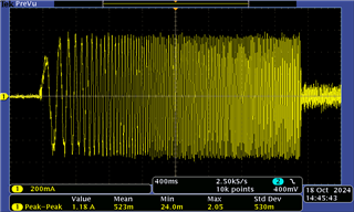
In the FOC tuning guide ( link , page 5) , it is mentioned that IPD startup method uses all three phase currents for detecting the initial position and to accelerate the motor in open loop mode until sufficient BEMF is achieved. The setup I am using has the LP-MSPM0G3507 and the DRV8329 EVM and using the example FOC code provided in SDK mspm0_sdk_2_02_00_05 . ( Motor link
In the tuning guide above, they recommend to use align and go as the startup procedure and it should work for most motors, however it just stalls when I try to do so . 


1. However, when I tried using IPD as the startup method , the motor successfully entered closed loop state and I am able to control the speed using the GUI successfully. The DRV8329 EVM has a single shunt setup only , still how is it running with IPD and not align or slow first cycle .
2. I have already tried doing the changes in the tuning parameters for both as mentioned in the guide but am still unable to get align and slow first cycle to successfully even enter open loop mode.

Thanks in advance,
Om Dave

  • I will find a motor expert to answer your question.

  • Hi Dave,

    Acutally I used to play with the EVM board and the motor you shared, it should work unless there is high load which makes it stalled. So, I suppose there might be some issue with your configuration.

    still how is it running with IPD and not align or slow first cycle .

    For single shunt resistor solution, although there only one feedback current in the bus, but it will detect twice within one PWM cycle, each could get a specifc phase current. After two phase current could be detected, then it could calculate the third phase current.

    I have already tried doing the changes in the tuning parameters

    I would recommend you check the align stage setting. Maybe you can share your configuration here.

    By the way, IPD is only to used for initial position detection, it is expected to work with align mode if you set little higher align current.

    B.R.

    Sal

  • Hello Sal,

    Thank you for you quick response
    I have attached the values of user_inp_mtr_startup registers. Please do let me know if any more register values are required. 
    After setting these values , I give the value of 3000 to the speedInput dialog box in the user control interface of the GUI (The value of 3000 is just something that works for me even while using IPD). The voltage drops to 5.7V from 24V supply and the current drawn is 2.5A (its the limit I have set on the power supply) for about 1 second , it does not trigger the over current protection of the supply but after one second , the voltage is back to 24v and 0A current draw. 
    In the GUI , it still shows in motor_align mode( in continuous read mode) .

    USER_INPUT_MTR_STARTUP1_T :0x0A949400

    USER_INPUT_MTR_STARTUP2_T: 0x53066006

    STARTUP1 ( Pic1)STARTUP1 ( Pic2)

    STARTUP2(Pic1)STARTUP2(Pic2)
    Thank you for helping me improve my understanding of IPD as well.
    Regards,
    Om Dave

  • Hello Sal ,


    I had one more question regarding the total DC bus current value . In FOC as you mentioned the phase currents are being sampled and estimated. However to get the total DC bus current , can I just use this Idc = k1*Ipha + k2*Iphb + k3*Iphc where the k1..3 are the gate commands 1/0 for the upper transistors?(or is there any better method )
    Or if the entire bus current is already being calculated in the algorithm , can I access it somehow ?

    Regards,
    Om Dave

  • Hi Dave,

    Sorrt for late reply, too busy these days.

    In the GUI , it still shows in motor_align mode( in continuous read mode) .

    By the way, please make sure you have modify the DRV8329EVM with the guidance in the SDK:

    This is important.

    Actually I do not play with the GUI, instead I use the CCS project to start evaluation. Please firstly check the hardware connection, and then I can help check with the GUI to see whether it could work.

    However to get the total DC bus current , can I just use this Idc = k1*Ipha + k2*Iphb + k3*Iphc where the k1..3 are the gate commands 1/0 for the upper transistors?(or is there any better method )

    In the signle shunt resistor solution, if you capture the bus current, you will find below waveform:

    This is what I tested with LP-MSPM0G3507 and DRV8329EVM.

    Actually you will get I1 and I2 from the bus current detection, then you can using k1*I1 and k2*I2 calculate the bus current average value.

    B.R.

    Sal

  • Hi Sal,

    By the way, please make sure you have modify the DRV8329EVM with the guidance in the SDK:

    We have done all the changes apart from the shunt resistor , the original resistor is retained on the EVM as we aren't able to currently change that, can that be the reason for align / slowFirstCycle not working as expected?

    Actually you will get I1 and I2 from the bus current detection, then you can using k1*I1 and k2*I2 calculate the bus current average value

    Will it be correct if we estimated the final phase value as well using Ipha + Iphb + Iphc = 0 (as being implemented in the code)  then use Idc = k1*Ipha + k2*Iphb + k3*Iphc rather than just two phases?


    Thank you ,


    Best Regards, 
    Om Dave

  • Hi Dave,

    We have done all the changes apart from the shunt resistor

    This is important.

    Actually 1mΩ is too small, and I used to play with 1mΩ, and it truns out not work. Then I choose to use 20mΩ.

    I suggest you change to 20mΩ and see whether it could work.

    Note: Please use one shunt resistor. I used to knwo a user who used three 7mΩ shunt resisotrs in series, and then the board also doesn't works well.

    Will it be correct if we estimated the final phase value as well using Ipha + Iphb + Iphc = 0 (as being implemented in the code)  then use Idc = k1*Ipha + k2*Iphb + k3*Iphc rather than just two phases?

    The waveform I showed is the real bus current.

    Ibus = k1*I1 + k2*I2 -> The k1 and k2 has the real meanings, which could be calculated by the PWM duty cycle.

    It could transfer to "Idc = k1*Ipha + k2*Iphb + k3*Iphc", while it is hard to tell the k1/k2/k3 real meaning. Maybe you can try to figure out the relationship, then it could work.

    B.R.

    Sal

  • Hi Sal,

    Actually 1mΩ is too small, and I used to play with 1mΩ, and it truns out not work. Then I choose to use 20mΩ.

    Okay thank you , I will try that .

    The k1 and k2 has the real meanings, which could be calculated by the PWM duty cycle.

    Could you please elaborate a bit more on how can I do this or if there is any resource I can refer to for achieving this , Thank you .


    Best Regards,
    Om Dave

  • Hi Dave,

    Could you please elaborate a bit more on how can I do this or if there is any resource I can refer to for achieving this , Thank you .

    This document give a brief instructions of how to achieve signle shunt soltion.

    https://www.ti.com/lit/an/spract7/spract7.pdf 

    Deriving the calculation formula for bus current requires some theoretical knowledge of motor control, but I currently do not have any relevant information to share.

    It not that difficult. Due to you just need figure out when apply an speicifc vector (PWM setting) into motor, then what the bus current is with this vector. Finally, you could figure out bus current calculation formula with all three vectors current (two effective vector, and one zero vector).

    B.R.

    Sal

  • Hello Sal,


    I researched about the current calculations for 3 phase systems and I still needed some clarity on the same .

    1. The phase currents that are being used in the FOC algorithm , are those the peak phase currents or the average phase currents ?
    2. I need to calculate the output RMS average current , the input dc current ( assuming 80% efficiency for now and PF as 1) and the peak output current .

    If you could please shed some light on how do I get these values from the phase currents that are being measured across the shunt resistor .

    Best Regards,
    Om Dave

  • Hi Dave,

    1. The phase currents that are being used in the FOC algorithm , are those the peak phase currents or the average phase currents ?

    Nope, FOC will using real-time current (Instantaneous value), it not peak or average one.

    2. I need to calculate the output RMS average current , the input dc current ( assuming 80% efficiency for now and PF as 1) and the peak output current .

    We do not implement this in our algorithm. So there is no refernce code or idea.- There are some ideas from my point of view. 

    RMS could be calculate by definition if user get the estimated speed to know the electrical cycle period time. Or, maybe use the peak value (maximum value) for simple usage.

    Regarding as DC input current, my idea is using the average current with all the phase current data you get in a whole electrical cycle, which used to calculate the average. The prerequisite is that you need to get the estimated speed to know the electrical cycle period time.

    B.R.

    Sal

  • Hi Sal,
    I got a 5mOhm shunt resistor for using align and slowFirstCycle startup methods  , however I am still facing the issue for moving into closed loop state while using slowFirstCycle and when trying to start using algin , the motor just moves a little and then stops . I have already tried increasing the current to 50% bus current , frequency to 20% of the maximum motor speed as recommended in the FOC tuning guide. Please let me know what register values shall I share in order for you to help me resolve this issue 
    I have currently attached mtr_startup regs

    /resized-image/__size/320x240/__key/communityserver-discussions-components-files/908/startupParameterVal.png

  • Hi Dave,

    It looks wired. Please try with the 20mΩ. 

    I will also verify the GUI and see whether it has any issues.

    I am expected update some progress within this week.

    B.R.

    Sal

  • Hello Sal,


    There is an inbuilt feature of FOC which triggers faults if the DC bus current exceeds a certain value .

    1.Could you please let me know how can we access the value of the bus current that is being used to generate the fault .

    2.Also I wanted to ask about the undervoltage, overvoltage and similar motor lock faults, I tried to use them to generate a fault and wasn't able to do so while referring to the FOC tuning guide. Could you please illustrate as to how can I use this feature and test it before using it in my application 


    Best regards,
    Om Dave

  • Hi Dave,

    Update some test experiments as you request.

    Using the GUI (Link) with the motor you shared, I verify it works well with GUI, which I use align/slow-first-cycle mode with 20mΩ in the board.

    #1 Align mode (current waveform)

    #2 Slow first cycle (current waveform)


    Within the test, I just do below change with the register value (I init it in the CCS project, this could also be set manually by GUI):

    Others keep unchanged with the default parameters.

    B.R.

    Sal

  • Hi Dave,

    1.Could you please let me know how can we access the value of the bus current that is being used to generate the fault .

    I suppose currently not detect the DC bus current, we check the phase current for the  current protection fault.

    Meanwhile, we do not have the interface to access it, I got feedback from SDK team that we will open interface in next version, currently we could implement the Power close loop which have calculated the bus current for power estimation.

    2.Also I wanted to ask about the undervoltage, overvoltage and similar motor lock faults, I tried to use them to generate a fault and wasn't able to do so while referring to the FOC tuning guide. Could you please illustrate as to how can I use this feature and test it before using it in my application 

    The resgister setting I suppose there has instructions in the tuning guide.

    The only thing user need to take care is that the based voltage.

    For example I set below:

    This means if dc bus voltage is over than 0.6*base = 0.6*76 =45V, or less than 0.2*76=15V; the fault will be triggered.

    Using clearfault could remove fault status after bus voltage recovered. Or set it automatically recovered.

    B.R.

    Sal

  • By the way, there has a updated GUI version for SDK 2.02, which might be helpful for you if you are using the previous one (previous one is the version I take the test and it could work).

    https://dev.ti.com/gallery/view/TIMSPGC/MSPM0G-SENSORLESS_FOC/ver/2.02.00/ 

    B.R.

    Sal

  • Hey Sal,

    Thanks for the reply, I will test the motor with the provided register values . I am unable to find the tuning guide for the latest GUI for the MaxMotorPower field in the system parameters. Is there a newer version of the tuning guide? The link in the latest readMe file of the latest SDK gives a 404 error 

    Best regards,
    Om Dave

  • Hey , 

    How is the estimated speed being calculated ? We are looking to implement stall detection so apart from the current sensing , we were looking for more options that can be used and is the same feature of motor lock and motor stall implemented in the current SDK ?

    Best regards,
    Om Dave

  • Hey Sal ,

    I am trying to compare the accuracy of the read phase currents to the actual phase currents in order to derive a relation to the DC bus current value for the motor stall feature . In the example code , we have the values of iabc raw which is in the IQ27 format , however even after conversions the values aren't very accurate to the values observed on a very accurate DMM . 
    I have used the _IQtoF function using mathAcl library , could you please guide on how can I correctly do the same .
    Also thank you for the register values sent above, I could successfully spin the motor using it even on 5mohm 

    Here rega is the same as iabc->a and is being updated at every single iteration of while(1) in the main function. rega is a int32_t and regb and regc are both float .

    Best regards, 
    Om Dave

  • Hi Dave,

    The link in the latest readMe file of the latest SDK gives a 404 error 

    You could use this one: https://www.ti.com/lit/ug/slau927a/slau927a.pdf 

    How is the estimated speed being calculated

    This is the achieved by eSMO. we do not open this for user.

    It could be achieved by abnormal BEMF detection, this is provided in SDK. -> This only takes effect in the closed loop.

    Here rega is the same as iabc->a and is being updated at every single iteration of while(1) in the main function. rega is a int32_t and regb and regc are both float .

    Recommend update the current once in the ADC interrupt. 

    B.R.

    Sal

  • Hi Sal

    I wanted to see how I can tune the parameter of maxMotorPower . This tuning guide doesn't have the instructions or the description of the parameter. All i know from the GUI is that the parameter is scaled from 0 to 1024 .
    I need to understand what value to put in the GUI in order to limit the output power

    Best regards,
    Om Dave

  • Hi Dave,

    I doesn't have a chance to play with power loop in demo.

    Firstly, I reccomend you work with load on motor, because if motor with no load, it will have a very small power consumption.

    Secondly, it just uses the power loop to replace the speed loop, then power loop control parameters and ouput configurations will be the same as the speed loop. The base power (or named max power) value will be set in System Parameters seperately.

    Thirdly, I got the feedback from software team that the new tuning guide is under review and takes some time to release to ti.com. You could firstly refer to the previous one.

    B.R.

    Sal