This thread has been locked.

If you have a related question, please click the "Ask a related question" button in the top right corner. The newly created question will be automatically linked to this question.

MSP432E401Y: SSI3 Read & Write

Part Number: MSP432E401Y

Tool/software:

Hello Team,

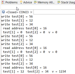
We have implemented the code for SPI based ethernet controller in which there is a driver provided by microchip on top of it we have added SSI functions. In the init for enc24j6 write and read 1234 is done. It is working only once that too if we flash and test in the below order

1.  flash with while(MAP_SSIBusy(SSI3_BASE)); (please refer the code snippet attached below) -> Slave out will return 1200

2. flash again by removing while(MAP_SSIBusy(SSI3_BASE)); -> Slave out will return 1234 as expected. This will also work as expected only once and even in the same debug session.

C1-> Clock  C2-> MOSI  C3 -> MISO  C4 -> CS

3. flash same code again -> Slave out will return 1200

We tried this order multiple times, same is happening.

Please find the below code snippet.

uint16_t ENCx24_Read(encX24J600_registers_t a)
{
  uint16_t v;
  uint8_t bank;
    bank = a & BANK_MASK;
    if(bank != UNBANKED)
    {
      ENCx24_BankselSPI(a);
      test[0] = (rcr_inst| (a & SFR_MASK));
      MAP_SSIDataPut(SSI3_BASE, test[0]);
      for(ii = 1; ii < 3; ii++)
               {
                MAP_SSIDataPut(SSI3_BASE, test[0]);
                MAP_SSIDataGet(SSI3_BASE, &test[ii]);
                //while(MAP_SSIBusy(SSI3_BASE));
               }
      ((uint8_t*)&v)[1] = test[1];
      ((uint8_t*)&v)[0] = test[2];


    }
    else
    {
        test[0] = (rcru_inst);
        test[1] = (a);
        for(ii = 0; ii < 2; ii++)
         {
          MAP_SSIDataPut(SSI3_BASE, test[ii]);
         }
        for(ii = 2; ii < 4; ii++)
                 {
                  MAP_SSIDataPut(SSI3_BASE, sendDummyData);
                  MAP_SSIDataGet(SSI3_BASE, &test[ii]);
                 }
      ((uint8_t*)&v)[1] = test[2];
      ((uint8_t*)&v)[0] = test[3];
    }
  return v;
}
#endif

We're not able to understand the behaviour happening here. Please help to find the issue.

Thank you in Advance

  • Hi,

      Can you clarify your problem? Your scope cap shows 1234 is returned. Are you saying the waveform is correct but you are reading 1200 instead? Or the slave is returning 1200 on the signals? Can you show 1200 that is returned by the waveform on the scope if this is the case?

      Why don't you show the waveform when while(MAP_SSIBusy(SSI3_BASE)) is added and also another waveform when while(MAP_SSIBusy(SSI3_BASE)) is commented out?

      What are you sending on MOSI? What value is it? I can't tell from your scope cap. Is it a read command? I'm not familiar with your ENCx24 chip. 

  • Hello Charles,

    Please don't see the above post, it is not working the same way right now. I will write the issue elaborately for you below


    In the initialization phase, the below instructions are done initially in which 0x1234 is written to a specific address XJ600_EUDASTL and then read back from the same.

    1. Write 1234h to EUDAST.

    2. Read EUDAST to see if it now equals 1234h. If

    it does not, the SPI/PSP interface may not be

    ready yet, so return to step 1 and try again.

    3. Poll CLKRDY (ESTAT<12>) and wait for it to

    become set.


    As in below oscilloscope images Master is writing the 0x56, 0x12,0x34 to the slave.

    Then Master is reading back the data by sending a command 0x16. slave is only returning 0x12. For providing clock and CS to the slave,i'm putting test[0]=0x16 in place of dummy data.

    Please find the code snippet


     do

            {

                ENCx24_Write( XJ600_EUDASTL , 0x1234 );

            } while(0x1234 != ENCx24_Read(XJ600_EUDASTL));


    void ENCx24_Write(encX24J600_registers_t a, uint16_t data)

    {

        uint8_t bank;

        bank = a & BANK_MASK;

        if(bank != UNBANKED)

        {

            ENCx24_BankselSPI(a);

            a &= SFR_MASK;

            test[0] = (wcr_inst | (a));

            test[1] = (((uint8_t*) &data)[1]);

            test[2] = (((uint8_t*) &data)[0]);

            for(ii = 0; ii < 3; ii++)

             {


              MAP_SSIDataPut(SSI3_BASE, test[ii]);

             }


        }

        else

        {

            test[0] = (wcru_inst);

            test[1] = (a);

            test[2] = (((uint8_t*) &data)[1]);

            test[3] = (((uint8_t*) &data)[0]);

            for(ii = 0; ii < 4; ii++)

                             {

                              MAP_SSIDataPut(SSI3_BASE, test[ii]);

                             }

        }

        while(MAP_SSIBusy(SSI3_BASE));

    }


    uint16_t ENCx24_Read(encX24J600_registers_t a)

    {

      uint16_t v;

      uint8_t bank;


        bank = a & BANK_MASK;

        if(bank != UNBANKED)

        {

                ENCx24_BankselSPI(a);

                   test[0] = (rcr_inst| (a & SFR_MASK));

                MAP_SSIDataPut(SSI3_BASE, test[0]);

    //tried adding while(MAP_SSIBusy(SSI3_BASE)); ->  gives a delay inbetween these commands and nothing changed

    for(ii = 1; ii < 3; ii++)

                         {

                          MAP_SSIDataPut(SSI3_BASE, test[0]);

                          MAP_SSIDataGet(SSI3_BASE, &test[ii]);

    //tried adding while(MAP_SSIBusy(SSI3_BASE)); ->  gives a delay inbetween these commands and nothing changed

                         }

                ((uint8_t*)&v)[1] = test[1];

                ((uint8_t*)&v)[0] = test[2];


        }

        else

        {

                  test[0] = (rcru_inst);

            test[1] = (a);

            for(ii = 0; ii < 2; ii++)

             {

              MAP_SSIDataPut(SSI3_BASE, test[ii]);

             }

                for(ii = 2; ii < 4; ii++)

                     {

                      MAP_SSIDataPut(SSI3_BASE, sendDummyData);

                      MAP_SSIDataGet(SSI3_BASE, &test[ii]);

                     }

                ((uint8_t*)&v)[1] = test[2];

                ((uint8_t*)&v)[0] = test[3];


        }

      return v;

    }

  • As in below oscilloscope images Master is writing the 0x56, 0x12,0x34 to the slave.

    My first question to you is if the master put the correct sequence of operations? Here you show on the scope cat that the master is sending 0x56, 0x12 and 0x34. Is this waveform correct per your ENCx24 device requirement? 

    Then Master is reading back the data by sending a command 0x16. slave is only returning 0x12. For providing clock and CS to the slave,i'm putting test[0]=0x16 in place of dummy data.

    My next question to you is if the scope cap is correct as required by ENCx24 for read? You show 0x16, 0x16, 0x16 sent out by the master? is this a correct sequence to read data? Again, I have no idea how ENCx24 device is supposed to work. If you believe the master has correctly sent the command sequence as in 0x16, 0x16 and 0x16 and the slave is supposed to return 0x00, 0x12, 0x34 then you need to check the ENCx24 what is wrong with the slave. Perhaps the command sequence is not correct but I can't help you to confirm if the command you sent is right or wrong since I'm not familiar with your slave device. The bottom line for you is to first answer if the command sequence shown on the scope by the master is correct or not. If the command sequence is not correct then I can help you debug why  the waveform is not matching what is written in your code. If the command sequence shown on the waveform is correct and you are not getting the right data out of the slave then you would need to consult with the slave device vendor. Show them the same scope cap and their experts should be able to pinpoint why the slave does not return 0x1234 as expected. Please understand I can only help on the MCU side, not the slave device. 

  • Hello Charles,

    Got it, thought this could be a issue with bus.. Will check in ENCx24 as you told.

    I have one other clarification

    In the current API, when the SSIDataPut() and SSIDataGet() functions are called, CS and Clock are enabled.

    While reading some data from the slave, it is required by the master to send some dummy bytes to enable CS and clock.

    Is it possible to control CS and clock pins manually without sending any dummy bytes from master to slave?

  • Hi Bala,

    Is it possible to control CS and clock pins manually without sending any dummy bytes from master to slave?

      You can use GPIO to control CS but for clock generation, you must call  SSIDataPut() with either a valid or dummy data to start transmission 

  • Hello Charles,

    I'm trying to write 0x1234 to an address and read the same address.

    With the oscilloscope snap below, it is clear that slave is fine. I also checked all the further instructions in oscilloscope those look perfect.

    C1-> Clock  C2-> MOSI  C3 -> MISO  C4 -> CS

    Terminal output:

    But in terminal/ expression viewer, it is reading from the first 0x00 and only at the third time it is getting 0x1234

    As per below code, i believe the controller reads the Slave out pin only when the 0xff dummy byte is sent. But it is reading from 0x00 in test[1] and test[2] for 4 times and at the 5th time it is 0x12

    uint8_t test[5];

    uint16_t ENCx24_Read(encX24J600_registers_t a)
    {
      uint16_t v;
      uint8_t bank;

        bank = a & BANK_MASK;
        if(bank != UNBANKED)
        {
            ENCx24_BankselSPI(a);
             MAP_GPIOPinWrite(GPIO_PORTQ_BASE, GPIO_PIN_1, 0x0);
            test[0] = (rcr_inst| (a & SFR_MASK));
            MAP_SSIDataPut(SSI3_BASE, test[0]);
             UARTprintf(" read address test[0] = %x\n", test[0]);
        
            for(ii = 1; ii < 3; ii++)
                     {
                      MAP_SSIDataPut(SSI3_BASE, 0xff);
                      MAP_SSIDataGet(SSI3_BASE, &test[ii]);
                      UARTprintf(" test[%d] = %x ",ii,test[ii]);
              
                     }
            ((uint8_t*)&v)[1] = test[1];
            ((uint8_t*)&v)[0] = test[2];
             UARTprintf(" v = %x\n", v);

            while(MAP_SSIBusy(SSI3_BASE));
             MAP_GPIOPinWrite(GPIO_PORTQ_BASE, GPIO_PIN_1, (GPIO_PIN_1));

        }
    }

    void ETH_SendSystemReset(void)
    {
        do
        {

            // wait until I can talk to the device
            do
            {

                ENCx24_Write( XJ600_EUDASTL , 0x1234 );

            } while(0x1234 != ENCx24_Read(XJ600_EUDASTL));


            g_SiliconRevVersion_u16 = ENCx24_Read(XJ600_EIDLEDL);


            while((ENCx24_Read(XJ600_ESTATL) & (ESTAT_CLKRDY /*| ESTAT_RSTDONE | ESTAT_PHYRDY*/)) != (ESTAT_CLKRDY /*| ESTAT_RSTDONE | ESTAT_PHYRDY*/));
            __delay_ms(1);


            // reset it to assure that it is in a fresh state.
            ENCx24_BFS(XJ600_ECON2L, ECON2_ETHRST);


        }while(0x0 != ENCx24_Read(XJ600_EUDASTL));

        __delay_ms(1);

        // all set...
    }

    Only after reading all the previous data, it is taking the right data. but that is in the wrong position.

    Since while(0x1234 != ENCx24_Read(XJ600_EUDASTL)); is happening until 1234 is returned, after the 00,00,00,00,12,34 again the same 00,00,00,00,12,34 will happen thrice. So the data read for     g_SiliconRevVersion_u16 = ENCx24_Read(XJ600_EIDLEDL);  line is coming only at this line   }while(0x0 != ENCx24_Read(XJ600_EUDASTL)); while reading in the terminal.

    I'm not able to understand what could be the issue. Kindly help me find the same.

    Thanks in advance.

  • Hi,

    But in terminal/ expression viewer, it is reading from the first 0x00 and only at the third time it is getting 0x1234

    As per below code, i believe the controller reads the Slave out pin only when the 0xff dummy byte is sent. But it is reading from 0x00 in test[1] and test[2] for 4 times and at the 5th time it is 0x12

    SPI performs full-duplex operations. When you send 0x56, 0x12, 0x34, 0x16, 0x16, 0x16, it will read six bytes of data in sequence which is 0x0, 0x0, 0x0, 0x0, 0x12, 0x34. In another word, after you send the 0x56 byte, it is receiving 0x0 at the same time into its RXFIFO. You seem to only use test[0], test[1] and test[2]. I think something got overwritten. Why don't you read the six bytes into test[5:0] and see if you have all the correct data and then process them. The 0x1234 should be in test[4] and test[5]. 

      I will suggest you also flush the RXFIFO before you start reading the slave. In your initialization for SSI, insert the below line to first clean out any residual data in the RXFIFO. See below example code. 

    //
    // Read any residual data from the SSI port. This makes sure the receive
    // FIFOs are empty, so we don't read any unwanted junk. This is done here
    // because the SPI SSI mode is full-duplex, which allows you to send and
    // receive at the same time. The SSIDataGetNonBlocking function returns
    // "true" when data was returned, and "false" when no data was returned.
    // The "non-blocking" function checks if there is any data in the receive
    // FIFO and does not "hang" if there isn't.
    //
    while(SSIDataGetNonBlocking(SSI3_BASE, &pui32DataRx[0]))
    {
    }