This thread has been locked.

If you have a related question, please click the "Ask a related question" button in the top right corner. The newly created question will be automatically linked to this question.

MSP432E401Y: MSP432E401Y + TUSB2046B USB no works

Part Number: MSP432E401Y
Other Parts Discussed in Thread: TUSB2046B, TPS2051B

Tool/software:

Hi TI,
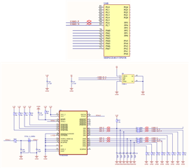
We have a design based on MSP432E401 that has a USB port via a TUSB2046B hub. Attached is the schematic.
The MSP432E401 works, however I am trying to run the example usbhostmouse_MSP_EXP432E401Y and the mouse is never detected.

Please any idea why the mouse is not detected? Do I need to do anything additional for the hub?

Thanks very much. 

  • I am using these pins on UART interfaces.

    Could this be the cause of my problem?
    Can I disable them in the firmware of the USB example firmweare to use them on the UART interfaces?

  • I am using these pins on UART interfaces.

    Could this be the cause of my problem?
    Can I disable them in the firmware of the USB example firmweare to use them on the UART interfaces?

     I don't understand what you mean to disable them in the firmware of the USB example. What is "them" that you want to disable? In general, you cannot use the same pin for two different functionalities (.e.g USB and UART at the same time) if that is what you mean to ask. 

     Have you run the example as-is on the LaunchPad? Can you confirm if it is working or not?

     I'm not familiar with TUSB2046B to comment if your connections to it is correct or not. Are you connecting a mouse to one of the USB ports on TUSB2046B?

     Have you tried to connect a mouse directly to MSP432E USB host port on your board bypassing  TUSB2046B  and run the usbhostmouse_MSP_EXP432E401Y example? This is one way to find out if there is an issue on your connections to TUSB2046B.

  • Hi Charles, Thanks very much for your reply.

    I am referring to PB0, PB1, PA6, PA7.
    PB0, PB1, PA6, PA7 on my board I use them for UART interfaces so I can use them on the USB.
    So I need to disable the use of Type Identification Pin, VBUS pin, External power enable pin, Power fault pin. Is this possible?

    I can't test the mouse directly to the MSP432 because I have it connected to the TUSB2046B on the board. As you see in the attached schematic DP0 and DM0 is the USB connection between the MSP432 and the TUSB2046B. The connection from the TUSB2046B to the mouse is through DP1, DM1.

  • PB0, PB1, PA6, PA7 on my board I use them for UART interfaces so I can use them on the USB.
    So I need to disable the use of Type Identification Pin, VBUS pin, External power enable pin, Power fault pin. Is this possible?

    Have you tried to keep these pins for USB and disable UARTs? Without the UART, does the USB host mouse example work?

    Also refer to the MSP432E System Design Guideline concerning USB. 

    4.3.1 USB Device

    For MSP432E4 MCUs that are used in a USB device configuration, the only signal used in addition to USB0DM and USB0DP is a GPIO to detect when 5 V is applied to or removed from the VBUS pin on the USB connector. For self-powered USB devices, software should monitor this GPIO and manage the internal USB PHY accordingly. If the microcontroller power is sourced or enabled by the VBUS pin on the USB connector, this GPIO connection is not needed. The only 5-V tolerant GPIO on MSP432E4 MCUs is PB1. For MSP432E4 MCUs that support OTG functionality, USB0VBUS is multiplexed with PB1 and should be enabled and used by software, because it is directly connected to the internal USB PHY. When used in a USB device configuration, a 100-Ω resistor should be placed in series between VBUS on the USB connector and PB1 on the microcontroller to limit damage which might be caused by an ESD event. If PB1 must be used for a function other than USB0VBUS, any other available GPIO could be used in its place. Because no other GPIO pins are 5-V tolerant, a 5.6-kΩ ±5% resistor in series with a 10-kΩ ±5% resistor should be wired as a voltage divider between VBUS on the connector and ground. This circuit drops the 5-V VBUS value to 3.2 V at the GPIO pin.

    4.3.2 USB Embedded Host

    For MSP432E4 MCUs that are used in a host configuration, the USB0EPEN and USB0PFLT signals may be used in the design in addition to USB0DM and USB0DP. These two signals typically connect to a power switch such as a TPS2051B, which controls power to the USB connector of the host. See the MSP432E4 device-specific data sheet to determine the ports on which these functions are available.

    4.3.3 USB OTG

    MSP432E4 MCUs that support USB OTG mode include the signals for USB Device mode, signals for USB Host mode and an additional signal USB0ID located on pin PB0. This USB ID signal is the 5th pin found on a USB micro-AB connector. If a micro-A cable end is plugged into this connector, the ID pin on the cable is tied to ground causing the MSP432E4 device to operate as a USB host. If a micro-B cable end is plugged into the USB connector, the ID pin is left floating. In this case, the internal pullup on the USB0ID signal causes the MSP432E4 MCU to operate in device mode. To limit damage from ESD events, a 100-Ω resistor should be placed in series between the ID pin on the USB connector and USB0ID (PB0) on the microcontroller. VBUS from the USB connector must be directly connected to USB0VBUS (PB1) of the microcontroller without a series resistor in between. In this case, USB0VBUS should be connected to an ESD suppressor such as a TVS diode, or ESD resistant VBUS switch.

  • Hi,

      I have not heard back from you. I will close the thread for now. If you have any update, please write to this thread and the thread will automatically change the status to OPEN.