This thread has been locked.

If you have a related question, please click the "Ask a related question" button in the top right corner. The newly created question will be automatically linked to this question.

MSP432E401Y: MSP432E401Y CUSTOM BOARD FLASHING ERROR

Part Number: MSP432E401Y

Tool/software:

Hello TI Members,

While flashing the code, i'm getting the error in one of the PCB(other boards are OK) based on the MSP432e401y micro-controller is as mentioned below.

" Error Connecting to the Target:

(Error-614 @0x0)

The target indicates there is an error condition from a previous SWD

request. Clear the error the condition, and try the SWD request again.

(Emulation package 9.12.0.00150)".

Kindly advise on the above.

Thanks.

Regards,

Kalyan.

  • Hi,

    While flashing the code, i'm getting the error in one of the PCB(other boards are OK)

    Can you tell me how many are ok? Is it only one that is getting an error?

    Has this board that is having problem been programmed in the past? Or this is the first time the board is programmed and you are seeing the error?

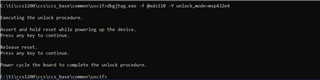
    Can you try to unlock the device to its factory setting. See below command. 

    .\dbgjtag  -f @xds110 -Y unlock,mode=msp432e4

    If you had successfully programmed the board in the past, do you still remember what code was in the device? Some low power mode code can turn off the clocks to the device and if the code does not provide a mechanism to wake up the clocks. When this happens, the debugger/programmer can no longer synchronize with the processor debug logic. 

    If this is a fresh/virgin device then can you check if there is good soldering on the PCB board especially for the JTAG pins?

    Can you do a ABA swap test by swapping a known good MCU to your board and vice versa. This will isolate the problem to the board or the MCU.  

  • Hello Charles,

    Can you tell me how many are ok? Is it only one that is getting an error?

    Has this board that is having problem been programmed in the past? Or this is the first time the board is programmed and you are seeing the error?

    --  Around 20 numbers are ok.

    -- This board was programmed earlier.

    Can you try to unlock the device to its factory setting. See below command. 

    -- Before powering on the board, I have shorted JTAG 9th pin & 10th  pin using a jumper. Then after power on, i executed the above mentioned command. Next, i removed the short while the board was on. However, issue was not resolved. Is it right way to do?.

    If you had successfully programmed the board in the past, do you still remember what code was in the device?

    -- Unfortunately, i didn't know what was the last code that was flashed in.

    Can you do a ABA swap test by swapping a known good MCU to your board and vice versa. This will isolate the problem to the board or the MCU. 

    -- Unfortunately, i didn't have a spare MCU to swap.

    Regards

    Kalyan.

  • -- Before powering on the board, I have shorted JTAG 9th pin & 10th  pin using a jumper. Then after power on, i executed the above mentioned command. Next, i removed the short while the board was on. However, issue was not resolved. Is it right way to do?.

    What JTAG header do you have? What is the purpose to short pin 9 and 10? I don't understand why you are doing that. 

  • What JTAG header do you have? What is the purpose to short pin 9 and 10? I don't understand why you are doing that. 

    I'm using 10 pin JTAG header and in that 10 pin connector pin3,5 and 9 are shorted to ground. 

    Since, in my board I didn't have a reset button, I have shorted reset pin(number 10) to pin 9 using a jumper and then I powered on board while connecting the xds 110 debug probe. 

    Later, inorder to release reset I removed the short in power on condition.

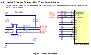
  • Refer to the recommended Arm-10pin JTAG header design in this app note. If you tie RST_N to ground then you are putting the device in reset. You should add a pullup to RST_N pin if you don't plan to use it. 

    https://www.ti.com/lit/pdf/slaa777

  • If you tie RST_N to ground then you are putting the device in reset. You should add a pullup to RST_N pin if you don't plan to use it. 

    I have pull up resister at RST_N node. 

    Since as per the sequence of unlock procedure, the first thing to do is "Assert and hold the reset while powering of the device".

    To meet this, i'm using the jumper to short RST_N to GND. Later for the second part inorder to release the reset, i'm removing the short.

  • Your pin 9 on the Arm 10pin header is tied to GND?

  • Your pin 9 on the Arm 10pin header is tied to GND?

    Ha, 9th  pin is connected to ground in my schematic as shown below.

  • Can you do a test connection? What is the result?

    In CCS, you can open the target configuration.  You can do a JTAG scan chain test connection.