This thread has been locked.

If you have a related question, please click the "Ask a related question" button in the top right corner. The newly created question will be automatically linked to this question.

MSPM0L1305: How to capture PWM in 0% or 100%?

Part Number: MSPM0L1305

Tool/software:

Hi Champs,

I am asking this for our customer.

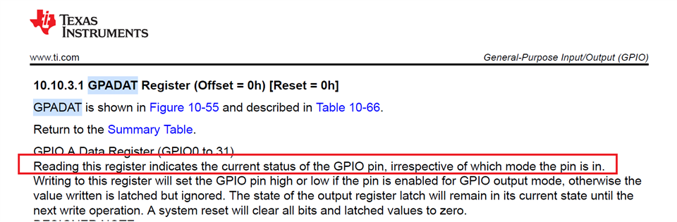
When using capture, is there any register/driverlib API to know if the input signal is kept in high or low?

For example, if the input PWM signal is 100% duty or 0% duty. How does MSPM0 capture it?

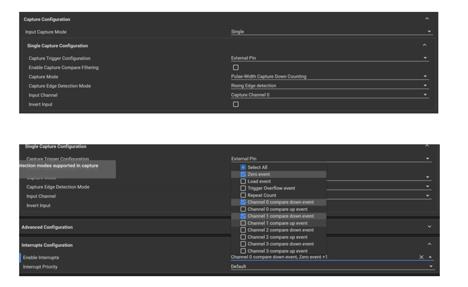
The user's setting like below.

  • What is there to capture? You would have to set up a time out in software and if you get no events in a certain time, assume it is CW.

  • Hi Keith,

    Besides software method, is there any register to understand the current status of the pin directly?

    That is, a register for the status of the GPIO pin no matter the GPIO is used as an capture input, PWM output, an I2C SCL, SDA, a UART TX/RX?

  • Generally the GPIO peripheral (PF=1) is disconnected when the pin is assigned some other function (PF>1). So as you say the peripheral would need to provide a pin-state capability [analogous to CCI in the MSP430 timers]. I didn't find one in the Timer peripheral. Except for the I2C (MBMON register), I haven't seen that capability in any of the other peripherals.

    It is theoretically possible to temporarily re-assign PF=1 in the IOMUX register and use the GPIO registers to read the pin state. When I tried that with timer-capture in particular, I got the correct results but I also saw glitches (false captures) apparently resulting from the IOMUX changes. My experiments [a half-hour with the Usual Suspects] didn't turn up a way to avoid this. My conclusion was that you really do need two (timer) channels to do PWM measurement.

  • Hi Bruce,

    Would you please give feedback to design to add this in the IP in newer devices?

    Without this, as you said, the user needs two timer module to handle this, which can have another resource issue.

    MSP430 and C2000 (called GPADAT) do have this register and can be useful in some cases including this post.

  • MSP430 and C2000 (called GPADAT)

    Hi Wayne,

    Not sure where you mean in MSP430's user's guide or c2000's TRM, state that the timer can capture a stable voltage without any edge? I think it is hard to do it in timer module to detect a stable voltage without pulse to calculate the duty cycle.

  • Hi Gary,

    We understand capture is used based on edge detection, so the user wants a simple level detection method.

    The user is asking a register to get the status of the pin irrespective of the pinmux used.

    Like this C2000 register, GPADAT

  • Just to be clear: PWM measurement here needs two timer channels (in one timer module) -- one for each edge. They read from the same pin (ISEL bits), and you know which edge it is by which channel triggered. In an alternate universe [CCI/GPADAT], it would be possible to set a single channel to trigger on "both" edges, then read the pin to see which edge it was.

    The timeout is a separable thing. It can be convenient to use the (N+1)-th channel on the same timer (same time base) for a Compare using the expected time of the next leading edge. In this case, N=2, and (I think) none of the L13x series timers has more than 2 channels, so you'd need a second timer module to do the timeout. (A pin-read facility could be useful for this as well, though that could instead be managed in software.)